The source of your issue isn't likely going to be the dialectric in your capacitors (this is audiofool talk, not a good way to start). Garbage electrolytics can sound excellent in a properly designed amplifier. Most of this amplifier is DC coupled (excellent design idea) so there aren't many caps in the audio path anyways. You likely just need to tune the operating points of the amplifier.
If you have a stage of the amplifier clipping badly or really heavy crossover distortion it will sound terrible. Different batches of transistors will act differently and often adjustments to the circuit are required to compensate for this (This is why I recommended you replace R11 with a pot so you can adjust output stage bias).
Have you measured the current flow through each section of the amplifier? Do they match what was recommended on the schematic?
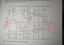
First step is to make sure output stage bias current is low so you don't burn out the output devices while testing. Measure the voltage drop across R19 or R20. 0.33 ohms * 0.1 amps = .033 volts so that would be the final adjusted voltage, but you don't want it that high yet. While tuning preceeding stages set this low, like 5mV by adjusting the pot at R11.
Next work at the input stage because the current flow through it will affect the following stages. It should be passing 2mA. Measure the voltage drop across R8 and use ohms law to calculate this. 300 ohms * .002 amps = .6 volts. It should be within 10% of this value. Q3 and Q4 make up a constant current source with R7 setting the current flow.
If the input stage is properly balanced and the input transistors are properly matched those 2 mA of current should be shared equally through Q1 and Q2. To check this compare the voltage drop across R1 and R2. This will affect the DC offset at the output of the amp and the cause of offset is usually poorly matched input transistors. Often there will be a pot between R1 and R2 to adjust the DC on the output, but crefully selected input transistors will get you close enough to run.
If you have a stage of the amplifier clipping badly or really heavy crossover distortion it will sound terrible. Different batches of transistors will act differently and often adjustments to the circuit are required to compensate for this (This is why I recommended you replace R11 with a pot so you can adjust output stage bias).
Have you measured the current flow through each section of the amplifier? Do they match what was recommended on the schematic?
First step is to make sure output stage bias current is low so you don't burn out the output devices while testing. Measure the voltage drop across R19 or R20. 0.33 ohms * 0.1 amps = .033 volts so that would be the final adjusted voltage, but you don't want it that high yet. While tuning preceeding stages set this low, like 5mV by adjusting the pot at R11.
Next work at the input stage because the current flow through it will affect the following stages. It should be passing 2mA. Measure the voltage drop across R8 and use ohms law to calculate this. 300 ohms * .002 amps = .6 volts. It should be within 10% of this value. Q3 and Q4 make up a constant current source with R7 setting the current flow.
If the input stage is properly balanced and the input transistors are properly matched those 2 mA of current should be shared equally through Q1 and Q2. To check this compare the voltage drop across R1 and R2. This will affect the DC offset at the output of the amp and the cause of offset is usually poorly matched input transistors. Often there will be a pot between R1 and R2 to adjust the DC on the output, but crefully selected input transistors will get you close enough to run.

^ This is excellent advice, that's how you do it. Let me just add one thing: when you install the R11 trim pot, make sure it's set to its maximum value (e.g. 1k if that's what you use, 2k2 would work too) before powering up. That way you ensure that the quiescent current starts low and later you can bring it up to its intended value safely.
I only have 10K potentiometers / trimmers. Would they work too?
All this measurements have to be done while powering the circuit with ±35V? I'm not very confortable with this but i will carefully give it a try...
All this measurements have to be done while powering the circuit with ±35V? I'm not very confortable with this but i will carefully give it a try...
10k would work but it would be hard to adjust. For now just remove R11. That will turn off the bias in the output stage completely and you can safely tune up the input stage. The feedback circuit will remove enough crossover distortion to make it work for now.
You should be tuning with it at operating voltage, but it should still operate about the same an lower voltage. Get the output stage shut down and test lower voltage. If nothing is getting hot, go full voltage after verifying the output stage doesn't have current flowing.
Normally when testing a new amplifier you would use a current limitter of some sort. Putting a 50W incandescant light bulb in series with the power supply mains works well for this.
Last edited:
You wil likely need some sort of heat sink on the driver transistors too. They will run warmer as you raise the voltage, A small scrap of aluminum sheet metal between them works good for this. By the time you have this amp tuned in and working properly you will likely have redesigned the bias spreader circuit and added a second heat sensing transistor to this heatsink.
We usually use a 200 or 500 ohm 20 turn pot. A 10k pot in parallel with another resistor to fine tune bias would work, but you have a lot of tuning to do before you need to worry about that.
I still do not understand why you would not use the completed and tested bc-1 design in chapter 4. That was the whole reason for doing it, so folks can build a complete design with ease apart from the mechanicals etc.
You can only use a fixed resistor Vbe bias generator in simulation because of variability in actual components.
You can only use a fixed resistor Vbe bias generator in simulation because of variability in actual components.
I tried other stuff, now the amplifier distorsion is very high at high frequencies and almost non existent at low frequencies. Whats going on!!?
Turning the bias trimmer makes completely no difference (i found a 3.3K one).
The currents on the output stage are very close to what they should be.
I also heat a faint... Like 6khz tone on the output speaker. Its oscillating!
So i guess that the main problem here is a BAD pcb layout...
Also, when i raise the volume a lot, another lower frequency superimposes itself on the output signal. (What the...)
At this point i can say that i just failed and i should make the complete amplifier directly with a better layout, if i can make it. (The complete version you are taking about)
Last edited:
Rick,
Sorry to bother - tried on a different thread for BC-1 but might have better luck here - would you have an Excel file for the BOM for the Protect circuits please?
Thanks
Neil
Sorry to bother - tried on a different thread for BC-1 but might have better luck here - would you have an Excel file for the BOM for the Protect circuits please?
Thanks
Neil
I tried Everything possible. The distortion at high frequencies remains and it is unfixable in this design. Even with the added components, this design is still probably incomplete. I even added a better feedback capacitor (47uF non polarized, i found it on an old crossover). No difference (And Maybe even if the feedback capacitor is ceramic it wont cause the distortion to be THAT BAD.) I mean it is really bad. It is basically unusable.
A real shame, but it is what it is. Gotta be careful from next time on.
A real shame, but it is what it is. Gotta be careful from next time on.
Did you measure the current in each section of the amp? Is it funcioning properly with no signal input?
Picking random capacitor values for filters isn't going to work. You need to do the math there. That feedback cap is more likely to affect low frequency though.
Picking random capacitor values for filters isn't going to work. You need to do the math there. That feedback cap is more likely to affect low frequency though.
The currents are fine. I have no clue of whats actually wrong.
Time to build a new amplifier i guess...
Time to build a new amplifier i guess...
I figured out that a polarized capacitor in the feedback also works without problems...
But after hours and hours of troubleshooting, i was never able to solve this problem.
All the currents are OK, all transistors are OK, the two power supplies i'm using to test this circuit are linear and contain 0 noise, i used the best quality components you could find, the PCB perfectly corresponds with the schematic because i completely 're-reverse' engineered it again with the multimeter, all transistors i used are from a legit company (Mouser), they are exactly the ones used in the schematic and i tested them for similar gain before mounting them, and all the transistors are cooled by a CPU cooler that can handle a TDP of 150w. (ALL of them are isolated with thermal pads and checked with multimeter for shorts).
Turning the bias potentiometer makes absolutely no difference in the distortion, it just increases the maximum power and idle current.
The audio input comes from a high grade preamplifier with high grade OpAmps that have a maximum distorsion of 0.000028%. (I mean, basically 0) (I bought this pre made and it was quite EXPENSIVE).
So, final verdict: The PCB layout is not good.
I admit defeat.
Have you got any proof of the preamp measured distortion?The audio input comes from a high grade preamplifier with high grade OpAmps that have a maximum distorsion of 0.000028%. (I mean, basically 0) (I bought this pre made and it was quite EXPENSIVE).
When i power the negative rail, the output of the amplifier is just DC voltage.
If i power the positive rail, it does not care at all (nothing happens).
If i power both, still always DC voltage on the output.
What are the exact values of the measured voltages?
Bob Cordells (Audio) amp book;-?
Now the amplifier works BUT there is a lot of distortion on the output at high frequencies. At low frequencies the distortion is much much lower.
The preamplifier is not the source of distortion (tested with another properly working amplifier).
The currents are very close to the ones in the book.
The preamplifier uses OPA1656 (More than one). In the datasheet the distortion is:
0.000029% (–131 dB) at 1 kHz
0.000035% (–129 dB) at 20 kHz
(For some reason i rembered 0.000028).
Still astoninglishy low. Those OpAmps are designed specifically for audio.
They also have
Ultra-low noise:
– Voltage noise: 2.9 nV/√Hz at 10 kHz
– Current noise: 6 fA/√Hz at 1 kHz
Yes, FEMTOAMPERE of noise. Those are quite top of the the line OpAmps, hence why the EXPENSIVE price.
My amplifier isnt working because of a bad PCB layout, at this point i'm 100% sure.
Last edited:
- Home
- Amplifiers
- Solid State
- Problem with dual supply amplifier (triple emitter follower)