Hi,
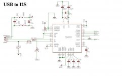
I have rigged up a circuit which is used for USB to I2s conversion..
I am using PCM2707 IC from Texas instruments...
And i have attached the schematic of my board also.. I am facing problems in making it recognized , meant to say that when i connect the PCB onto USB port.. A message pops up on windows saying USB not recognized...
I dont know what fault is in my Schematic.. I cross checked the wiring , the components many times .. but didn't find any mistakes..😕
Can anyone please guide me in getting the work done...
Thank you,
Kitty
Attachments
I believe pin 3 (HOST) should have a connection to Vcc.
Some designs have it connected to VCC and some to ground.. I tried both combinations but didnt work

Take a look on the configuration i use for PCM2706.
Uploaded with ImageShack.us
An externally hosted image should be here but it was not working when we last tested it.
Uploaded with ImageShack.us
Take a look on the configuration i use for PCM2706.
Thanks for the circuit... But i don find much changes in yours and mine.. Mine is Bus powered and yours is Self powered.
Then you have connected all the Analog Vcc's to 3.3V and i have connected to ground.. I think , this will not be of much concern..
But whats that AND gate doing with that HOST pin???
The gate is there to prevent HOST detection while the DAC is powered off; the chip can be configured to run bus-powered.
Does your PCM2707 chip oscillate ? Is your USB connector wired correctly ?
Does your PCM2707 chip oscillate ? Is your USB connector wired correctly ?
Does your PCM2707 chip oscillate ? Is your USB connector wired correctly ?
U meant does the 12Mhz oscillate ?? i checked with an CRO for it i got a near 12MHz oscillation..
USB is wired correctly , is there anyway to check whether PCM is dead or working??
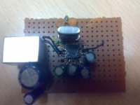
Yes, i mean if the 12MHz oscillates. The 1M ohm resistor and ~27pF capacitors are critical, the chip will not work without them, even if you see oscillation. Show us a photo of your PCB, maybe we can spot something.
Yes, i mean if the 12MHz oscillates. The 1M ohm resistor and ~27pF capacitors are critical, the chip will not work without them, even if you see oscillation. Show us a photo of your PCB, maybe we can spot something.
I am onto it as a prototype , so my PCB is still on its way... i have a not so good picture of it , but i don think you will be able to track the lines and all sorry....
Attachments
Successsssss!!!!!!!!!!!
I am able to get the PCM detected..
All the pull ups which were given to 5V were given to 3.3V.. I used a 5 to 3.3V regulator and it worked...
It detects as an USB Audio device...
This comes up in the Control Panel => Sounds and devices..
But when i connect my I2S output lines to a Transmitter which has the I2S inputs m not able to receive any audio...
Is there anyway i can verify that audio is been streamed through PCM???
Whats the format of the I2S out ???
Is it ----
Standard I2S
Left Justified (16, 18, 20 or 24 bits)
16 bits Right Justified
18 bits Right Justified
20 bits Right Justified
24 bits Right Justified
Please do guide me???
Is it ----
Standard I2S
Left Justified (16, 18, 20 or 24 bits)
16 bits Right Justified
18 bits Right Justified
20 bits Right Justified
24 bits Right Justified
Please do guide me???
What exactly is this 'transmitter' you are using ?
I connect the PCM to a sample rate converter, i never tested the analog outputs or other functions of the chip. But you might want to test if your chip's analog outputs are working.
I connect the PCM to a sample rate converter, i never tested the analog outputs or other functions of the chip. But you might want to test if your chip's analog outputs are working.
I cant name it but it has I2S , analog and SPDIF inputs.. Atleast i i can verify that the analog out is working then it would be fine i think..What exactly is this 'transmitter' you are using ?
Yes i want to do this , what all changes should i make... is only VoutR and VoutL enough??? should i pull up all the Vcc R,L,P to 3.3V???But you might want to test if your chip's analog outputs are working.
You should read the datasheet again carefully.
First of all, you must make sure that the FSEL pin is low for I2S output. Otherwise SPDIF output is selected.
I think the audio analog outputs are always active.
First of all, you must make sure that the FSEL pin is low for I2S output. Otherwise SPDIF output is selected.
I think the audio analog outputs are always active.
When i connect my module to USB port , it is detected as a USB Audio device and falls under " Sound, video and game controllers " in the device manager..
I checked the Frequency on I2S lines ,
SCLK = 12.20 to 12.31 MHz
LRCLK = 48 KHz
Bit CLK = 2.8 MHz
Is there anywhere i am wrong , please do correct me...
I checked the Frequency on I2S lines ,
SCLK = 12.20 to 12.31 MHz
LRCLK = 48 KHz
Bit CLK = 2.8 MHz
Is there anywhere i am wrong , please do correct me...
- Status
- Not open for further replies.
- Home
- Source & Line
- Digital Source
- Problem with connecting PCM2707 to USb