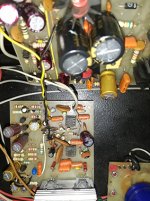
Hi. All the components in this list are ok. The bias current is the issue. It is not achieving the 10 mA. I have done all the measurments indicated in the manual. The same conection points described in the procedure.This might be more legible.
Can you go directly to the emitter resistors instead of the test points? This is where many Marantz manuals have a problem.
Craig
Craig
Yes, it is playing. Did not input signal and load to verify with osciloscope. Until I cant discover why it is not raising to the recomended level,Supposedly the amp plays OK just can't set idle current.
Craig
I will do this way.Can you go directly to the emitter resistors instead of the test points? This is where many Marantz manuals have a problem.
Craig
Please dont laugh. In the diagram, wich one is the spreader transistor. Never heard this designation.Should measure about 1.2 V at the collector of the bias spreader transistor.
This amp doesn't have the typical Vbe multiplier type bias spreader but you can measure base to base voltage of H721 and H723 drivers, should be about 2.4VDC, which is the voltage for 4 B-E PN junctions in series. Each driver and output transistor B-E will drop about .6VDC, so 4 x .6 = 2.4VDC. This voltage should vary with R733/R734. The lower the voltage the colder the bias.
Craig
Craig
Last edited:
I fixed an old Amp 2x250W Rms it has four pairs mj15003 and mj15004 and a Darlington driver 2n5015 with bux67 and 2n3440 with bux66 (I don't remember which is pnp and npn) but I am sure for the numbers. But I'm not sure for the Vbe if I put it about 500mv transistors get very hot quickly if I keep it about 380mv then temperature is not too high I can touch them what is the best option?
Attachments
it is an old amp hand made Brand (Solitaire) no schematic Good sound I bought it because of the out put transistors.
The technician who made it erase the transistor numbers from the protection circuits on purpose.
Service was a challenge for me. I change all caps sound is very clear. for me
Main Voltage is +62V 0 - 62V
The voltage between the base of 2n5015 -2n3440 is 3Volts and between bux67 -bux66 is 2Volts
I am not sure for the Vbe of mj15003 and mj15004 why to put it at 600mv it gets too hot quickly the drivers don't have o good cooling system the out put transistors have a fan might be ok? but driver don't I don't know what to do?
Transistor amp power stages are not normally biased by Vbe. It is too variable, especially with heat.
Normally we find small (part Ohm) series resistors in the output stage, and adjust for 10mV-40mV across them.
Normally we find small (part Ohm) series resistors in the output stage, and adjust for 10mV-40mV across them.
Thank you. Will try and post the reading.This amp doesn't have the typical Vbe multiplier type bias spreader but you can measure base to base voltage of H721 and H723 drivers, should be about 2.4VDC, which is the voltage for 4 B-E PN junctions in series. Each driver and output transistor B-E will drop about .6VDC, so 4 x .6 = 2.4VDC. This voltage should vary with R733/R734. The lower the voltage the colder the bias.
Craig
Hi, I did the measurmet as you said. I am reading 2,1 volts. But it is not going up or down when R733/734 increased or decreased.Thank you. Will try and post the reading.
- Status
- Not open for further replies.
- Home
- Amplifiers
- Solid State
- Problem in adjusting bias in a Marantz 1070


