Go for it!
You found additional parts somewhere? Or just managed to expose the hidden leads? Good work in any case!
You found additional parts somewhere? Or just managed to expose the hidden leads? Good work in any case!

I had a better look at the transformer that jumped away during transportation 😉Go for it!
You found additional parts somewhere? Or just managed to expose the hidden leads? Good work in any case!

So I guess I will have to disassemble the little board on which the transformer was mounted and desolder the four pin which I understand were actually part of the transformer (!!!) and fix them back to it.
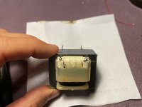
One question: the four leads have an insulating sheath, how do I remove it to be able to solder them?
One question: the four leads have an insulating sheath, how do I remove it to be able to solder them?
Attachments
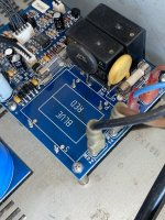
Look beneath the PCB. If there are no tracks You could fix the transformer to the PCB and then drill a hole in order to zip-lock it.
It does look possible. One option might be to thread some medium gage (tinned) copper wire through where the pins were (if these are fully drilled) and loop the wire back to secure it. Then you might be able to solder the loose ends of the coil to these wires. They could be soldered to the PCB as a sort-of replacement pin too, if sturdy enough. Seems there might be a little space between the back of the bobbin and plastic cover without hitting the coil?
Not ideal to have exposed metal at main power line voltage but you could tape over the connections once you check it works (without touching the primary that is!) (or before repositioning on the PCB if you confrim the connection with a meter)
Careful - but I agree it is worth a shot.
Not ideal to have exposed metal at main power line voltage but you could tape over the connections once you check it works (without touching the primary that is!) (or before repositioning on the PCB if you confrim the connection with a meter)
Careful - but I agree it is worth a shot.
Earlier years I was tempted to repair headphone coils.
Those are a pita to be seen or to be soldered.
They tend to flee when touched with the iron.
In Your case I think it's doable because I can see 4 wires.
Those are a pita to be seen or to be soldered.
They tend to flee when touched with the iron.
In Your case I think it's doable because I can see 4 wires.
We use 600 or so grit abrasive paper to strip insulating varnish.
A gentle twisting movement works.
It also prepares the surface for soldering, a slightly rough and freshly cleaned surface is good to solder.
Epoxy in gel or putty form to fix posts.
But check the transformer before adhesive stage.
A gentle twisting movement works.
It also prepares the surface for soldering, a slightly rough and freshly cleaned surface is good to solder.
Epoxy in gel or putty form to fix posts.
But check the transformer before adhesive stage.
Last edited:
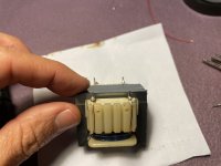
Looks like I did it! (What a pain to solder the thin leads, the tin just wouldn’t stick on them..)
Resistance on the pins of the secondary (thick leads) is 3.7 ohm, while between the pins of the primary is 800 ohms, does it make sense?
How can I test it?..
Resistance on the pins of the secondary (thick leads) is 3.7 ohm, while between the pins of the primary is 800 ohms, does it make sense?
How can I test it?..
Attachments
- Home
- Amplifiers
- Solid State
- Problem Harman Kardon power amplifier