This is incorrect. You've stated information that is inaccurate if the xover is other than a 1st order. Changing the impedance will shift the Q of the filter, not the xover point in higher than 1st order networks.
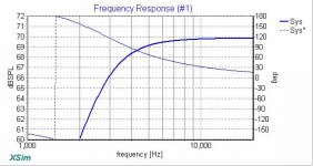
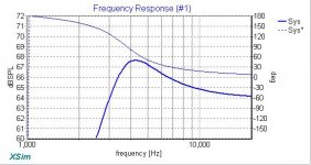
The simulations below show the actual values of the Super Tower Butterworth high pass filter terminated by 8Ω, and then by 16Ω to simulate a light bulb filament of 8Ω in series to nominally drop the voltage across the tweeter by nominally 6dB. You can see that the -3dB point relative to the passband drops from ~3300Hz down to ~2600Hz with the simulated light bulb in circuit.
Attachments
Last edited:
I'm sorry, but what you are showing does not show a shift of xover frequency. It only shows that the FR of the tweeter has changed, as any value or parts change will result.
Wolf
Wolf
For high power zeners stud modern mount devices are a fraction of the price of outdated T03 devices. The zeners Electro-Voice used were rated at 50W, total overkill for a domestic application. 5W zeners would be more than adequate and are typically less than $1 each in single quantities.... that is a no for the TO3 zeners. They are either $160 each, or largely unavailable.
Furthermore, you should be looking at the -6dB point for an in-phase xover at Fc, or it will sum with a peak of +3dB instead of flat. -3dB points mean more in woofer alignments than in-phase xovers, UNLESS you prefer a BW3 alignment.
Wolf
Wolf
Let's just agree then that the -3dB point relative to the passband has reduced in frequency and the average spectral balance in the HF output has also shifted down in frequency. The salient point is that the level of protection for the tweeter is less than what might be intuitively expected.I'm sorry, but what you are showing does not show a shift of xover frequency.
Last edited:
My comments are specific to the crossover of the speaker system that the original post is about, that's all.... UNLESS you prefer a BW3 alignment.
Last edited:
What your graphs actually show are an increase in Q of the filter, and a further attenuation above there. They do not show that the xover point has moved. This common reaction that the xover point has shifted is stated more often than it is correct. The resonance of the parts in the xover are still resulting at the same frequency, but the Q has changed due to a different impedance than optimal, and is no longer optimal for that resulting load.
For example, when you double the impedance of a driver and leave the xover alone, the Q will double, or induce a peak at the knee. If it was a BW 0.707 Q, then textbook relays this to now be 1.414 Q and obviously peaking.
Not that we actually calculate Q for every filter we design, but this is how it works.
I did not look up the xover info about the design in question to know what 's xover looks like, nor do I know the goals of the designer of the loudspeaker. Sure though, the tweeter might be a little more stressed, if it were not for the added attenuation.
You cannot however know the response of the tweeter and how the network affects it, as you did not have measured responses of the tweeter used in the cabinet intended. You were modelling with a resistive load, and not an actual impedance, nor real frequency response.
Wolf
Last edited:
Wolf, I accept everything in your post in relation to filter design, including that the load does not change fc, merely Q (obvious, when you think about it). However as I said previously I was posting about the specific HPF of the system under discussion in the original post, and then only in relation to the effect of using a light bulb to limit the thermal dissipation in the connected tweeter. I accept that I used the term 'crossover' incorrectly, but semantics don't invalidated the points I was making in relation to this topic. When I used the term 'crossover' I was talking about the spectral content of the tweeter and its filter in isolation, not the alignment of the system or even the HF part part of the alignment, because the context of the problem being discussed is protecting the tweeter with a bulb. At my age I am not always as lucid as I might aspire to be. I think for the sake of the thread we should move on.
Last edited:
- Home
- Loudspeakers
- Multi-Way
- ProAc Super Tower 1st edition blowing tweeters