Attached is the belly of my 2nd ever build. Completed earlier this year, but have gone back to it to change a few things. Biggest is some hum. I want this dead quiet! I know I have a lot to learn about proper grounding techniques, so I'm spilling my amps' guts out for you guys.... About my notes: All ground points are underlined in "pink"; eyelet board layout is (from left): preamp/DC caps/phase inverter/(some open space)/tremolo section. Questions: Should I twist the green filament wiring? Should the input jack be insulated from the chassis? The tremelo ground wire is long, goes to the phase inverter ground point (lug to eyelet board mount stud). I tried to keep each "section" a separate ground, and the guitar input at the far end of the board, away from the electrolytics. Appreciate all critique and suggestions! P.S. There is a pwr tube bias pot next to the spkr jack; and there is no tone stack in the build (yet) - just put a pot in there for later. Thanks!
Attachments
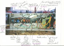
The heater wires need twisting.
Try to run heater wires away from signal wires.
After that you need a star ground system with a single connection point at the power supply.
Try to separate the power supply ground. The charging pulses into the smoothing capacitors can modulate the ground line and cause serious hum.
A couple of years back I designed a mixer and just the laid the pcb out the way it came from the schematic. When I powered it up I had 1 volt of hum on the output !!!
I realised the power supply charging pulses were in with the signal ground and was modulating it.
So I redesigned the pcb with the smoothing ground going to the edge of the pcb where the power ground came in. This time I got pretty much zero hum.
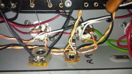
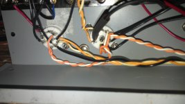
I just redid the heater wires - see attached. No change.... Will make sure the power supply ground(s) are all by themselves. And should this point be as far away from other ground points as possible (and keeping lead length to a minimum)? Thanks!
Attachments
Just read thru the Valvewizard write-up, and WOW was I doing things wrong....using the chassis as a ground plane, willy-nilly grounding, and with the PT secondary center-taps grounded as well... Ouch! I'm gonna lift the whole circuit off the chassis - including input & spkr jacks - totally floating, and connect the circuit ground busses ala fig 15.5b (to minimize ground loops within the circuit). Hoping for amazing results! Thanks!
You still must ground 2 points to the chassis. The mains earth (green cable) and the input jack (maybe through 2 antiparallel diodes)
Costis - this is for electrical safety sake? Chassis to earth, guitar to chassis (to earth)? Makes sense. Thanks
Yes it is for safety. If you enclose anything electrical in a metal box, the box must be connected to safety ground in the event of something shorting to the box. This is especially important with instrument amplifiers because the musician is usually in contact with the chassis via the strings of the guitar.
As far as using a ground bus care is still taken to keep larger currents away from sensitive input stage currents, meaning you can still get loops. A star ground is yet a better way to do grounding.
As far as using a ground bus care is still taken to keep larger currents away from sensitive input stage currents, meaning you can still get loops. A star ground is yet a better way to do grounding.
And be aware there are many sources of hum that have zero to do with grounding.
Heater to cathode current for example.
Determine if you have 60Hz or 120Hz hum, or both. They come from different sources.
Heater to cathode current for example.
Determine if you have 60Hz or 120Hz hum, or both. They come from different sources.
And be aware there are many sources of hum that have zero to do with grounding.
Heater to cathode current for example.
Determine if you have 60Hz or 120Hz hum, or both. They come from different sources.
60Hz is from heater supply or magnetic coupling from transformers.
120Hz is from poorly smoothed supply.
I had an interesting fault on a mixer pcb.
If I cascaded 2 stages in the same valve there was no hum.
If I cascaded 2 stages across different valves there was hum.
It seems the 2 stages inside the same valve had hum which was cancelling !
In the end the hum was coming from a too close transformer.
It wasn't the heaters as I checked with a DC heater supply and the 50 Hz hum was still there.
Last edited:
Costis - this is for electrical safety sake? Chassis to earth, guitar to chassis (to earth)? Makes sense. Thanks
Connecting to mains earth is for 2 reasons (a) safety. and (b) giving it a zero volt reference to everything else.
The way to do it without creating a ground loop is to connect it at ONE point per transformer primary and secondary.
Which means I forgot to mention that you should also connect the 6,3V secondary to chassis ...
 .. Again at one point, either the center tap of the 6.2 winding or through two 100 R resistors (valvewizard has the schemes)
Connecting to mains earth is for 2 reasons (a) safety. and (b) giving it a zero volt reference to everything else.
It's purpose is for safety only. Using the chassis for a 0 volt reference is purely for convenience. OP's intentions are to avoid ground loops by not using the chassis as a reference.
It's purpose is for safety only. Using the chassis for a 0 volt reference is purely for convenience. OP's intentions are to avoid ground loops by not using the chassis as a reference.
As I pointed out, there should be only one connection to each of the secondaries to 0 Volt (chassis) This avoids the ground loop problem.
- Status
- Not open for further replies.
- Home
- Live Sound
- Instruments and Amps
- Princeton clone hums - analyze my build?