Hello,
I have a 12W 211 amp, which was finished by a friend who cannot recall all details and the amp is currently waaay tooo HEAVY to move easily from it's position on a shelf without a lockdown illegal additional pair of hands.
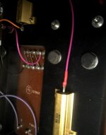
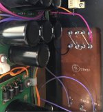
I have been taking some images with a phone from the underside to see what I can learn and this has prompted a couple of questions on impedance. Of course all will be answered to some extent with my ears once I can move the damn thing and rewire the output transformer to see but in the mean time for my much needed education:
I have 8 ohm speakers, the output is currently wired to 16 ohms, who will this affect the performance.
The primary is wired to 10K, but has a 7.6K option, and this suggests as mine is 1000V and 12 W class A design I should consider the 7.6K....
http://www.tubecollectors.org/archives/vt4c.pdf
BUT everyone seems to sell 10K primary output transformers for the 211 (does everyone expect to run 1250V?)
Thanks
I have a 12W 211 amp, which was finished by a friend who cannot recall all details and the amp is currently waaay tooo HEAVY to move easily from it's position on a shelf without a lockdown illegal additional pair of hands.
I have been taking some images with a phone from the underside to see what I can learn and this has prompted a couple of questions on impedance. Of course all will be answered to some extent with my ears once I can move the damn thing and rewire the output transformer to see but in the mean time for my much needed education:
I have 8 ohm speakers, the output is currently wired to 16 ohms, who will this affect the performance.
The primary is wired to 10K, but has a 7.6K option, and this suggests as mine is 1000V and 12 W class A design I should consider the 7.6K....
http://www.tubecollectors.org/archives/vt4c.pdf
BUT everyone seems to sell 10K primary output transformers for the 211 (does everyone expect to run 1250V?)
Thanks
Attachments
10k is fine, just rewire the secondary to 8R. Speaker impedance is not a fixed value anyways and varies with frequency. With the 16R OPT secondary, the reflected impedance of your 8R speaker is 5K, which most likely gives you a worse distortion scheme - whether this is audible or not...😕
Thanks - so for the 211 specification sheet for 12W class A at 1000V why is 7.6K quoted, and different specific values for other anode voltages?
Very simplified explanation :
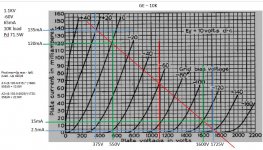
If you see the tube's curves and the loadline (this sample is 10k loadline), it seems. that lower load (for example 7k6) is less steep.
The less steep loadline collides to recommended maximum power curve (simplified each curve end points represents it) at higher anode voltage, so lower load usable at lower voltages.
This will results lower output power, and more or less greater distortion.
Attachments
One of the problem that normally is not considered is the real load of a power stage.
Due the variable impedance of loudspeaker the real curve is not a line but it is elliptical so other considerationa must be done.
This elliptical shape is variable with the type of real load.
I my opinion is always better to use a single secondary taking the ratio a little bit higher than normal.
Just an example, if I decide to use 10 k for a 211 ( it is reasonable), I will set the secondary to 5 or 6 ohms.
In this way when the Z load decrease ( for baass reflex it happen two time normally) in every case the reflected impedance is high enough to get a good energy tarnsfer.
When th Z load increse I will have a greater Z reflected but it is better for distortion; regarding power this is not a proble because we are speaking not rms power but impulsive.
Walter
Another angle on your question is that GE gave several examples from the world of transmitters, where maximum output driving resistive loads from available voltages is the goal. Driving elliptic loadlines and loudspeaker damping are not considered, because what kind of nutjob would even be able to afford type 211s to drive speakers in 1939? (Except Western Electric!)
YOS,
Chris
YOS,
Chris
Yeah, I would agree. Moving the idling point up and left, then making the nominal load light enough that fatter non-resistive loads still fit, is the ideal solution. This is how we would choose a loadline for any other stage, but we tend to get all macho about the output stage.
"Mine makes more power than yours". Says everybody, all the time, as if 2dB peak always and automatically matters. And intrinsic distortion and speaker damping don't. But that's life on the interweb.
YOS,
Chris
"Mine makes more power than yours". Says everybody, all the time, as if 2dB peak always and automatically matters. And intrinsic distortion and speaker damping don't. But that's life on the interweb.
YOS,
Chris
Magnepans actually act like a pure resistance. Not all speakers are reactive. Just wanted to add this and prevent misinformation. But 99% are...
Very lossy speakers can be somewhat resistive, or at least not as inductive as most, over part of their range, but all speakers have fundamental mass x compliance resonances, which is easily seen in an impedance sweep.
Horn loading also damps the fundamental resonance if it's within the horn's working range, leaving the driver's inductance. Inductance can be dealt with by paralleled Zobel networks, so a dedicated amplifier for a single driver could see a fairly resistive load.
But fundamentally, all speakers are somewhat reactive. They're motors, so it's not surprising. And amplifiers can be designed to drive them linearly. Nothing new.
YOS,
Chris
Each bass reflex speakers have a double peak around the low-mid range where the energy is great.
And they are a majority of speakers sold.
So the peak means that there is a inductive and capacitive loads and the phase is changing.
This can be a problem.
Just an example from Audioreview magazine here in Italy ( where I write); a test on Yamaha NS3000 in black the curve of modulus and red the phase.
It is possible to imagine how is the real elliptical curve .
Walter
Attachments

Ideally, 211s work even better with an even higher load, like 15K-20K primary OT impedance. Sowter has a suitable OT they make for this purpose. Power output suffers a bit but distortion goes way down. 211s are hard to drive, an RC coupled stage like most amps have, does a lousy job. a cathode follower or IT drives the 211 much better.
Ideally, 211s work even better with an even higher load, like 15K-20K primary OT impedance. Sowter has a suitable OT they make for this purpose. Power output suffers a bit but distortion goes way down. 211s are hard to drive, an RC coupled stage like most amps have, does a lousy job. a cathode follower or IT drives the 211 much better.
So I found this information and it got me thinking.
J&K Audio Design: 211 tube loadline
16K is preferred logically here, and I have a 10K (or 7.6k) primary transformer and 8 ohm speakers (now on an 8 ohm tap) which sounded better than the 16 ohm, but not dramatically so to be honest.
SO if I put the output on 4 ohms and the primary on the 7.6K which is a separate primary tap (see picture) and connect my 8 ohm speakers...do I get a reflected 15.2K so it would behave more like a 16K primary winding, OR do the laws of real physics not really work like this?
Thanks,
Attachments
They do work like this, but only at the midband.
7.6k seems to be just the tap on the "full" 10k primary and therefore it provides lower inductance than the whole primary. The bass response (and also efficiency) will suffer.
On the secondary side it depends. It's always better to use all of the secondary sections from the HF response perspective. So if 4 Ohm secondary is obtained by interconnecting all of the sections (some in parallel), it's fine. If it's just the tap on the 8 or 16 or whatever Ohm secondary, or is obtained by interconnecting some of the sections, it's not.
They do work like this, but only at the midband.
7.6k seems to be just the tap on the "full" 10k primary and therefore it provides lower inductance than the whole primary. The bass response (and also efficiency) will suffer.
On the secondary side it depends. It's always better to use all of the secondary sections from the HF response perspective. So if 4 Ohm secondary is obtained by interconnecting all of the sections (some in parallel), it's fine. If it's just the tap on the 8 or 16 or whatever Ohm secondary, or is obtained by interconnecting some of the sections, it's not.
Well I don't think I will attempt this yet, especially as I am trying to first determine what's going on with my HF response (see my other thread on this).
Yeah all sections in secondary are in parallel or series to obtain the right impedance.
Thanks for the insight
oh I suppose I could also leave the 10k and end up with ~ 20K reflected?
I use 99 db/W Klipsch speakers so not many watts required
I use 99 db/W Klipsch speakers so not many watts required
- Home
- Amplifiers
- Tubes / Valves
- Primary Impedance for 211 in Class A [Newbie]