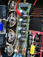
This seems to be a beginners amp, at a quick look i identified C5 and C6Thanks to mravinsky for the schematic which the cayin ta-35 which is similar if not the same as the prologue 5
View attachment 799298
who will have overvoltage at power-on. ( 407V at one side, -30V at the other
while spec at 400V)
Maybe this is a reason not to supply schematics
Do not change the capacitors - all these MKPs are ok. Nothing is burned or looks like damaged by heat.
The first thing I would check are the bias voltages of the output tubes and the bias voltage supply. As far as I understood, both channels are affected.Bias voltages can be checked as well as plate and G2 screen voltages of the output tubes. Depending on the installed output tubes you can look up in the valve datasheet if the measured voltages will make any sense.
The first thing I would check are the bias voltages of the output tubes and the bias voltage supply. As far as I understood, both channels are affected.Bias voltages can be checked as well as plate and G2 screen voltages of the output tubes. Depending on the installed output tubes you can look up in the valve datasheet if the measured voltages will make any sense.
Next step would be the supply voltage for the input tube(s). Left and right channel have one common supply of 200V regulated by a zener diode. A failure of the zener could bias the input tube and/or phase splitter completely on or off. When switching of the amp, voltages will go down and you get a somehow reasonable biasing of the input section even if the zener is open.
Next step would be the supply voltage for the input tube(s). Left and right channel have one common supply of 200V regulated by a zener diode. A failure of the zener could bias the input tube and/or phase splitter completely on or off. When switching of the amp, voltages will go down and you get a somehow reasonable biasing of the input section even if the zener is open.
Aboos this is great information and makes sense thank you for your input this gives me more confidence to source the problem and solve it.
Sure beats my mention of a plate fuse, but thanks to you and rayma for taking the trouble to recognise my contribution! 🙂Aboos this is great information and makes sense.
Sure beats my mention of a plate fuse, but thanks to you and rayma for taking the trouble to recognise my contribution! 🙂
There are often hidden fuses around, even inside transformers, and in speaker enclosures (thermal tweeter fuse/switch).
Last edited:

OK guys the strangest thing happens, I played music through the amplifier and when I measure the voltages across the these capacitors (bias board) the sound returns to normal? If I do this for each one it works, but as soon as I disconnect the test leads the sound goes back to being low and crackly??
All the voltages seem to be OK, am I missing something. Why does the sound go back to normal when I measure across the these capacitors?
Hi !
catching up late, but just to mention that the big Solen Caps are not the correct value. Originally they should be 0.1uF and NOT 10uF. Replace them with the correct value and smaller footprint. You can try to install them more to the front just above the small tubes sockets. The output tubes radiate more heat.
The film caps on the Autobias board are coupling caps on the signal path.
Mario
- Home
- Amplifiers
- Tubes / Valves
- PrimaLuna Prologue 5 Issue and schematic