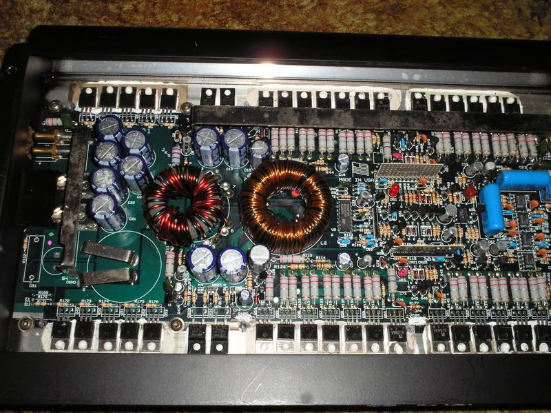
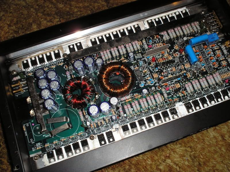
I just got one on egay for pretty cheap, I needed something to match the A600 I'm running my mids on. The guy told me it was .5ohm stable and ran 800wrms at 1 ohm mono. I don't believe it can do that with one 60 amp fuse (that's what my A600 has) but I do believe it could put 600 clean watts out at that load. The deal is I opened it to see if there are any differences from the A600 (because the shell is exactly the same, only black and a different model name) and I noticed the power supply filter caps are 50v on either rail, I believe the A600 is the same. It also uses the same model number and quantity of output transistors and power supply mosfets. In fact it looks the same except for the power resistors, this one has them for the collector and emitter apparently.😕 Is that the only reason it is .5 ohm stable, because there are some extra resistors to soften the load on the output transistors?😕 I would think the power supply rail voltages would be lower and there would be more output and power supply transistors. Is this amp good for 600 well damped watts, or what? Any opinions welcome, thanks.
hi ppia600,
wow .5ohm stable!..i'd expect a lot of mosfet switchers & output tranies for that to be realistic..unless the mosfets & tranies used are so powerful...😀
i don't know the specs of that amp though
what are the supply rails @ that rated load?
wow .5ohm stable!..i'd expect a lot of mosfet switchers & output tranies for that to be realistic..unless the mosfets & tranies used are so powerful...😀
i don't know the specs of that amp though
what are the supply rails @ that rated load?
It's common for PPI to use multiple parallel 0.68 ohm emitter resistors. There are no resistors in series with the collectors.
I have an art series a600 here now and it has two parallel 0.68 ohm resistors on each emitter.
The rail voltage is likely much less in the promos amp. That alone would allow it to drive a lower ohm load than the a600.
I have an art series a600 here now and it has two parallel 0.68 ohm resistors on each emitter.
The rail voltage is likely much less in the promos amp. That alone would allow it to drive a lower ohm load than the a600.
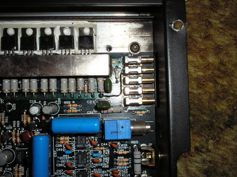
Thats why I'm wondering why there are 50V caps on each side of the rail😕 That would seem like a waste, wouldn't it be better to use a lower voltage/higher microfarad cap instead? It has evidence of being repaired too, there is a thin solid strand wire soldered from the channel closest to the speaker terminals directly to one of the terminals. Maybe one of the tiny fusible resistor/jumpers blew and they didn't feel like pulling the entire board to replace it. Everything else looks oem like its never been touched though. I'll be putting it in today hopefully, to see how it compares with the earthquake D2. Maybe the woofers and the mids will be more in phase with eachother now that I have two of basically the same amps and the crossover is built into the deck.
It's possible that they use the same exact board as another amp but install a different transformer.
Lower voltage, higher value caps may be marginally better but would not make an audible difference.
Lower voltage, higher value caps may be marginally better but would not make an audible difference.
Well, I got it installed today and..
-WAY less power than the earthquake phd2
-Distorts WAY sooner than I'd expect (the phd2 had almost none)
-Runs SUPER hot even at low volume levels, the A600.2 I have running my four mids and tweets runs cool compared to the mos50
I'm running the mos50 at 2 ohms bridged, using two mtx t7500's that are rated at 400wrms each. I guess they are kind of heavy for the ppi, but sheesh I didn't expect such a drop in spl and rise in distortion
Would running it at 1 ohms bridged make it substantially louder and also maybe magically make it run a little cooler since the output voltage will be lower??? I mean I know I've been griping about the phd2 dropping volume at a certain level, but I'm almost contemplating putting it back in.
Running it a 1 ohm is going to make it run hotter. If it's getting really hot really quickly at 2 ohms, 1 ohm will likely cause it to fail.
Does the amp get hot at idle? If so, the biasing may be too high or the amp could have other problems (leaking outputs, defective drivers...)
If you ever have the two amps apart, you should measure the rail voltage to see how much they differ.
The distortion is likely because you were running it to clipping. Below clipping, the distortion levels will be below audibility unless the amp is damaged.
Yeah, I realize it is clipping. It just happens way earlier than I would expect. I'm just used to the phd2 I guess. And the phd2 having such a steep slope on the built in crossover really helps the crossover from midwoofers to subs. The ppi doesn't have one and I'm using the internal one on my Kenwood deck which supposedly has an 18db slope but doesn't sound like it.
What I will do in a few minutes (just finished completely lowering my car and changing several mounts) is take a ride for about thirty minutes with the radio on and volume turned way down, I will check and see if the amp gets hot. If it does I will check to see if the bias setting has been tampered with next time I get a chance to remove the amp from under the seat. I guess I'll also remove the board from the sink and check underneath to see if there are any problems with cracked joints or bad transistors. The low impedance light never comes on so I don't see any bad problems with the power supply transistors or outputs but maybe a driver in between isn't working or one of the vertical ceramic boards has a problem. I did try both channels independently in the house before installing it and they both played clearly and sounded like both sides of the sound wave were there.
My next goal will be to find a manual with specs and see if I'm running it correctly. I've had the other pro mos amps with the white heat sinks and fins, and I know they are stable into 1 ohm each channel, but I've never seen an art pro mos in person so I don't know how I should be running it. Either way I will pull it apart next time I get a chance, I was just anxious to see how it sounded. Thanks for the replies
🙂
What I will do in a few minutes (just finished completely lowering my car and changing several mounts) is take a ride for about thirty minutes with the radio on and volume turned way down, I will check and see if the amp gets hot. If it does I will check to see if the bias setting has been tampered with next time I get a chance to remove the amp from under the seat.
I guess I'll also remove the board from the sink and check underneath to see if there are any problems with cracked joints or bad transistors. The low impedance light never comes on so I don't see any bad problems with the power supply transistors or outputs but maybe a driver in between isn't working or one of the vertical ceramic boards has a problem. I did try both channels independently in the house before installing it and they both played clearly and sounded like both sides of the sound wave were there. My next goal will be to find a manual with specs and see if I'm running it correctly. I've had the other pro mos amps with the white heat sinks and fins, and I know they are stable into 1 ohm each channel, but I've never seen an art pro mos in person so I don't know how I should be running it. Either way I will pull it apart next time I get a chance, I was just anxious to see how it sounded. Thanks for the replies
🙂
Need to find the actual specs, picture..
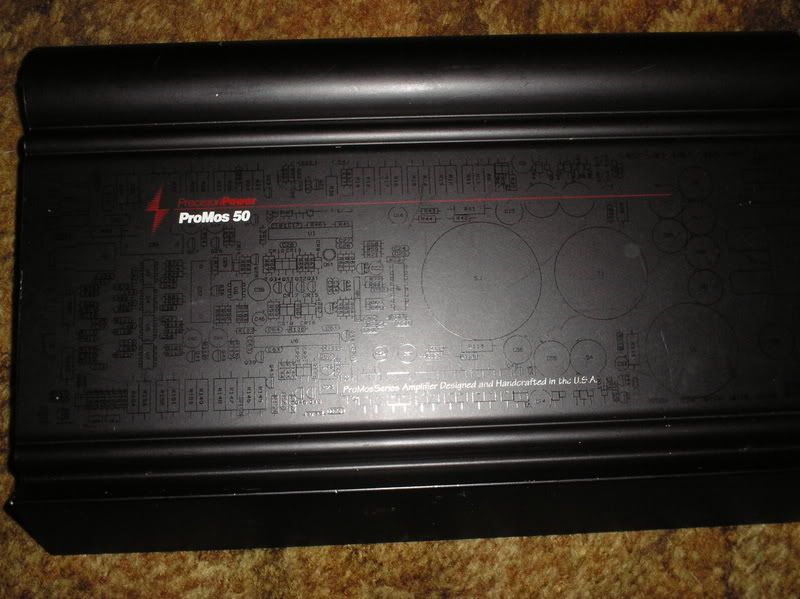
Does anyone know where I could get actual specs on this amp? I contacted a person who buys and sells amps on ebay, he sells manuals for ppi as well. (Didn't get my amp from him) Of course he didn't have a manual for the amp I have. He told me he is suspicious of my amp because he says they didn't make any pro mos 50 in the art style housing. Mine is obviously genuine, down to the worn silk screening. Here's a pic from the ebay listing. It actually has all of the schematic silk screening still, just can't see it from this angle:

Does anyone know where I could get actual specs on this amp? I contacted a person who buys and sells amps on ebay, he sells manuals for ppi as well. (Didn't get my amp from him) Of course he didn't have a manual for the amp I have. He told me he is suspicious of my amp because he says they didn't make any pro mos 50 in the art style housing. Mine is obviously genuine, down to the worn silk screening. Here's a pic from the ebay listing. It actually has all of the schematic silk screening still, just can't see it from this angle:
Wow, I just went to ampguts.com and they have pics of pretty much every amp you can think of, inside and out. The only amp that is the same is the A600.2, it looks exactly the same on the inside as my "pro mos 50" except mine is all black.😕 I am going to go take it out of the car now and take it apart completely. Maybe this one is modded to not protect because I know neither my old A600 or my current A600.2 will run 2ohms mono without making horrible noise and making the low impedance light come on. Maybe I will be able to find out how the low impedance function has been bypassed or modified, I have a feeling its the jumper wire I wrote about previously. Wow, this is weird, the amp appears to be un molested on the outside.
?????????????????????
The only amp that is the same is the A600.2, it looks exactly the same on the inside as my "pro mos 50" except mine is all black.😕 I am going to go take it out of the car now and take it apart completely. Maybe this one is modded to not protect because I know neither my old A600 or my current A600.2 will run 2ohms mono without making horrible noise and making the low impedance light come on. Maybe I will be able to find out how the low impedance function has been bypassed or modified, I have a feeling its the jumper wire I wrote about previously. Wow, this is weird, the amp appears to be un molested on the outside. ?????????????????????
Here are a few pics, the white one is from the amp guts site, it is an a600.2, the last one is after I completely regreased the transistors and under the insulators as well. The wire jumper is just completing a circuit that was previously completed by one of the small 1/8 resistor sized jumpers. It isn't bypassing anything, just goes a different route. You can see it soldered to one of the output terminals, they did a good job. There aren't any shorted transistors or broken traces or cracked solder joints, everything seems to be normal. Maybe I am going to have to run this at 4 ohms mono since the art amps actually drop power output when you run a lower than recommended load. Looks like my next subs will have to be dual 4 ohm voice coils per sub. So basically if this is an a600.2, I have been only getting about 300wrms because of the 2ohm bridged load. No wonder it sounded so much weaker than the phD2.
No wonder it sounded so much weaker than the phD2.An externally hosted image should be here but it was not working when we last tested it.
Well I forgot to check the rail voltage when I had the amp apart but I did check the output voltage on a constant tone/level test cd at work. I had a power supply connected to the car to be sure the battery voltage stayed constant. The maximum continous ac voltage without any audible distortion was between 39 and 40 volts. This was at any load I tried.. 8 ohms bridged, 4 ohms bridged, or even 2 ohms bridged. I'm convinced it is meant to be ran at 2 ohms for maximum output even though it gets pretty hot. I think I'll just mod it for coolant and leave it at that. If it work as well as the last a600 I used coolant with, I will be happy. For some reason today when testing it seemed to have plenty of output unlike the first day I installed it.😕 Maybe pulling it apart, going over the solder joints, and regreasing everything helped. I still have to pull it apart one more time.. I think it has the dreaded staticky noise and I'm hoping its not one of the vertical ceramic boards..
Almost forgot to ask. On the bottom left corner of my last picture, you can see there are spots for two capacitors, a choke, and a couple of resistors on this amp as well as in my a600.2. What was the point of tracing the board for them if they weren't being installed? There is even a notch on the huge jumper for the electrolytic cap to clear😕
but I did check the output voltage on a constant tone/level test cd at work. I had a power supply connected to the car to be sure the battery voltage stayed constant. The maximum continous ac voltage without any audible distortion was between 39 and 40 volts. This was at any load I tried.. 8 ohms bridged, 4 ohms bridged, or even 2 ohms bridged. I'm convinced it is meant to be ran at 2 ohms for maximum output even though it gets pretty hot. I think I'll just mod it for coolant and leave it at that. If it work as well as the last a600 I used coolant with, I will be happy. For some reason today when testing it seemed to have plenty of output unlike the first day I installed it.😕 Maybe pulling it apart, going over the solder joints, and regreasing everything helped. I still have to pull it apart one more time.. I think it has the dreaded staticky noise and I'm hoping its not one of the vertical ceramic boards..Almost forgot to ask. On the bottom left corner of my last picture, you can see there are spots for two capacitors, a choke, and a couple of resistors on this amp as well as in my a600.2. What was the point of tracing the board for them if they weren't being installed? There is even a notch on the huge jumper for the electrolytic cap to clear😕
I have never seen a pro mos using the art series heat sink before!!!
Do check out the rail voltages and post them up for both the pro mos and the art series I would be interested to know what they both are...
Do check out the rail voltages and post them up for both the pro mos and the art series I would be interested to know what they both are...
Hey I thought that you may find this interesting...
http://ampguts.realmofexcursion.com/PPI_ProArt_50/
So this one is a Pro Art 50, yours is a Pro Mos 50, they are most likely the same thing......
http://ampguts.realmofexcursion.com/PPI_ProArt_50/
So this one is a Pro Art 50, yours is a Pro Mos 50, they are most likely the same thing......
Yeah, I had already checked there and you can see in that picture there are way more capacitors on the power input section near the fuse. The board is even configured differently for the capacitors. I wish mine had all of those caps to help filtering be even better than it is now. I'm really wondering if this thing was modded by ppi (or someone else) to run the higher current load. I will check the rail voltages asap, just don't feel like pulling both seats to check and having to line the screws back up that hold the amps down. I also need to be able to find the two points to use for testing for the positive and negative sides of the rails. I'm also thinking of adding two more woofers outside of the car to see if the low impedance light comes on. I'm curious how much of a load it will take to make it come on????
When I get the chance to check voltages I should be able to just flip the amps upside down and pull both covers while they are installed, I'll just have to be careful to check quickly to keep any transistors from getting hot.
When I get the chance to check voltages I should be able to just flip the amps upside down and pull both covers while they are installed, I'll just have to be careful to check quickly to keep any transistors from getting hot.
To stop the transistors getting too hot just remove the rca input cables....
No signal, no current through the output devices....
No signal, no current through the output devices....
I was actually going to use two shorted rca caps to completely eliminate any noise/hiss in the preamp circuits. They are just two rca connectors with the positive and negatives soldered together. 🙂
Ok, today I got a chance to check both amps' rail voltages in the car.
A600.2:
test point 1 -38.7 vdc
test point 4 +38.7 vdc
Pro mos 50:
test point 1 -23.2 vdc
test point 4 +23.2 vdc
(the test points were on the output side of the power supply output filter choke. both amps had the same printed numbers)
So apparently the power supply does have lower voltage and it has been modified to run that way. 2 ohms is the optimum bridged mono load, or 1 ohms stereo. That is good to know. But now there is something ELSE I am curious about: Does the pro mos have a built in subsonic filter to prevent excessive power output or to optimize it for spl? I notice its frequency response below say... 30 hz sucks. It seems to go into a cancel out mode like the subs are out of phase at any bass note below approximately 30hz. The earthquake I have will play notes so low you can see the trunk move back and forth slowly. I realize it takes more power to produce super low notes but back when I had an A600 running my two premier 12's bridged into a 4 ohm mono load, it would play every note down to about 20hz. You couldn't HEAR every note, but you could feel it.
Could they have possibly put different capacitors on the input side of the board to limit frequency respoinse????
- Status
- Not open for further replies.
- Home
- General Interest
- Car Audio
- precision power pro mos 50, good stuff?