this is a circuit i ve been building designed from rod
this is the wave form in the output on frequency 28.500 hz square wave
question :
A) you may notice that square wave gets rounded from this frequency point (28500 hz) and then gets almost triancle at 100 khz
is this normal ?????
B) the circuit is designed arround NE5532 but strangelly TL082 seem to behave the same regarding frequency response what will determine that 5532 is better than TL082???? is there any other way to mesure this ???? or simply take it as a fact that 5532 is better than TL 082 ???
C) finally is there any other better way that will make 5532 perform perfect square wave till 100 khz ?????
thank you
Attachments
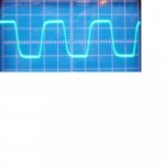
A square wave consists of a lot of sinewaves, starting with the main frequency and then all odd harmonics. Like, if you have a 1kHz square wave, that is built from sine waves at 1kHz, 3kHz, 5kHz, 7kHz etc. Now, if you put that in an amp that at some point has a decreasing freq response, the higher frequency components get more attenuated. That causes the sharp edges of the square wave (which depend on the higher freq parts) to disappear and the wave gets rounded.
Since ALL feedback amplifiers at some point start to show falling freq response, it happens with all of them. But, for audio, this is pretty much moot because your amp is flat to 10's of kHz. What you see in your 28kHz square wave (which of course has nothing to do with an audio signal anyway) is probably because of falling freq response above 100kHz or so.
Makes sense?
Jan Didden
the 5532 does better than that
maybe a problem with your implementation or the measurement?
Project 02 uses uncommon high resistance values.
Rod Elliott has a forum on his own. Maybe he would answer performance issues with his circuits? 😕
regards
maybe a problem with your implementation or the measurement?
Project 02 uses uncommon high resistance values.
Rod Elliott has a forum on his own. Maybe he would answer performance issues with his circuits? 😕
regards
janeman
yes it makes sense and more or lees is understandable .... but then what ???? i forget this circuit and built my shelf a doz preamp or other that will perform perfectly till 100 khz as stated ????
is all this a procedure that will guarantee better sound quality for the regarding stage ????
is this the correct procedure to see if you really have a good preamp in your hands ????
thanks
i will try to see about simular circuits with ne 5532 and get back to you ....i may be post in esp forums also
thank you very much
Juergen Knoop said:the 5532 does better than that
maybe a problem with your implementation or the measurement?
Project 02 uses uncommon high resistance values.
Rod Elliott has a forum on his own. Maybe he would answer performance issues with his circuits? 😕
regards
i will try to see about simular circuits with ne 5532 and get back to you ....i may be post in esp forums also
thank you very much
Re: janeman
nope
nope
nope
sakis said:yes it makes sense and more or lees is understandable .... but then what ???? i forget this circuit and built my shelf a doz preamp or other that will perform perfectly till 100 khz as stated ????
is all this a procedure that will guarantee better sound quality for the regarding stage ????
is this the correct procedure to see if you really have a good preamp in your hands ????
nope
nope
nope
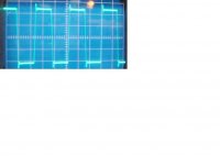
you were very correct
i forgot that i was making these tests with the original cable of my signal generator that is 50ohms cable .....
i replaced the cable and see what i get now @ 28.500 hertz
Juergen Knoop said:the 5532 does better than that
maybe a problem with your implementation or the measurement?
Project 02 uses uncommon high resistance values.
Rod Elliott has a forum on his own. Maybe he would answer performance issues with his circuits? 😕
regards
i forgot that i was making these tests with the original cable of my signal generator that is 50ohms cable .....
i replaced the cable and see what i get now @ 28.500 hertz
Attachments
tschrama
.......i would love to here your approach ...except nope nope nope
thanks
tschrama said:
nope
nope
nope
.......i would love to here your approach ...except nope nope nope
thanks
topward 8110
topward 8110
also this distortion you see on the edges i dont know were does it come from
topward 8110
also this distortion you see on the edges i dont know were does it come from
The overshoot at the edges is the opposite to what you had before. Now the higher harmonics are stronger than the base frequency, you now have a freq response that goes up with frequency instead of down. For example, you have a resistor in series with the input and a capacitor across that resistor that favours higher frequencies. It could be the cable.
Jan Didden
Jan Didden
it could be the scope cable. more cable capacitance will cause the edges to be rounded, less capacitance (and some wiring inductance, i suspect) will cause the overshoot. oscope inputs aren't completely "plug and play", as every scope has frequency compensation that must be matched between the probe, cable and scope. since the input impedance of a scope is usually 1 Meg, a small change in capacitance makes a large change in the frequency response of the complete measuring "system". if you doubt this, figure out what capacitance would have an Xc of 1 megohm at 100khz. now figure out how much of a capacitance change would make Xc equal to 1.1 Meg, and also for 0.9 Meg (a 10% change. you will find it's very small. that is why your probes and cables must be compensated with a capacitance that matches the capacitance of the scope input. if you take a probe with compensation cap, and attach it to the pin or ring on the front of the scope marked CAL, and adjust the compensation trimmer, you will see a large change in the shape of the 1khz square wave. how much more sensitive is this adjustment at 100khz????????
thanks uncle jed
this is actually allready done ..... i have a quiet expensive probe and its calibrated to my scope's input ....
on the other hand expept that friend who gave me a nope nope nope do you agree with procedure ???
this is actually allready done ..... i have a quiet expensive probe and its calibrated to my scope's input ....
on the other hand expept that friend who gave me a nope nope nope do you agree with procedure ???
Re: thanks uncle jed
You could check your source at the input to see if it is different. If it also has the 'square wave distortion' you know it's not the amp.
Jan Didden
sakis said:this is actually allready done ..... i have a quiet expensive probe and its calibrated to my scope's input ....
on the other hand expept that friend who gave me a nope nope nope do you agree with procedure ???
You could check your source at the input to see if it is different. If it also has the 'square wave distortion' you know it's not the amp.
Jan Didden
Square wave response of NE5532 preamp
To make the thing short, bellow it is the response curve of a preamplifier implemented with NE5532s in a 10KHz square wave in its input which produced from a HAMEG 8130 function generator (Ft=10MHz, rise/fall time<10nsec). The supply level of preamp is +/-18Vdc. Its sound performance is pretty good. This can give a better idea to Sakis.
Regs
Fotios
To make the thing short, bellow it is the response curve of a preamplifier implemented with NE5532s in a 10KHz square wave in its input which produced from a HAMEG 8130 function generator (Ft=10MHz, rise/fall time<10nsec). The supply level of preamp is +/-18Vdc. Its sound performance is pretty good. This can give a better idea to Sakis.
An externally hosted image should be here but it was not working when we last tested it.
Regs
Fotios
- Status
- Not open for further replies.
- Home
- Amplifiers
- Solid State
- Preamplifier wave forms