I have build this preamp, but the sound is to light.
does anyone knows what to change to get more mid
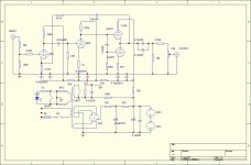
thanks see schematic
Increase the value of the coupling capacitors if possible.
Start by increasing the coupling caps. The one between the two 6N4's need to be 220 nF minimum (1/(220E-9 F * 1E6 Ohm) = 2.2 Hz). The one by the 12AU7's should be 100 nF min. This will give you less than 0.5 dB attenuation at 20 Hz.
Then I suggest moving the volume control to the input. I would change the 100 kOhm on the input to 1 MOhm. Connect the ends of the volume pot between the input connector and ground; connect the wiper to the input of the amp. Scrap the 50 kOhm resistor currently present on the input.
If this arrangement causes clipping in the input stage at high volume, you can add 10 kOhm from the input connector to the top of the volume pot.
If this doesn't improve the sound quality, I'd reduce the 9.09 kOhm on the output to something like 100 Ohm (or eliminate it completely).
~Tom
There is a lot of circuit there, just to give you a gain of about 6. It looks like it was designed by someone whose day job is in solid-state.
Changing capacitors as tomchr suggested will not make much difference, except possibly to introduce motorboating (LF oscillation), as there is heavy negative feedback via the 24.3K resistor.
There seems to be a mistake in the circuit. I assume the output stage is supposed to be a White cathode follower. If so, the 0.1uF capacitor joining the 12AU7 grids should go from the lower grid to the upper anode. Is it built correctly, or did you build the circuit as shown? Correct this, and see what happens.
As it is a line stage the volume control should be at the input, as tomchr says. The 9K at the output seems daft. You have lots of circuitry to generate a low output impedance then you throw it away with a big series resistor. I would suggest something between 100ohms and 1K here.
The 3.3uF in series with the 24.3K will give you a rising response below about 2Hz. Don't use this line stage after a phono preamp, unless the preamp has extremely good subsonic filtering or your records/turntable have no rumble/warps! The small coupling caps will help prevent this getting out of hand - maybe that is why they are small.
It looks like it was designed by someone whose day job is in solid-state.
I'd guess shoe sales- this is a terrifically incompetent circuit. Not quite as bad as the Lampizator I was just looking at, but close. Overload performance is guaranteed to be awful, linearity is... questionable, and the noise performance will be very sub-par. The "designer" has no idea of how to run heaters. The output impedance is totally destroyed by that 9k09 and the volume control.
Where does this stuff come from?
I thought Mr. Lampizator is regarded as a guru - although I must admit I struggled to understand his site. I was never clear whether he was struggling with English (quite understandable) or physics. There were probably a few gems there, but the effort of digging became too much for me.
I have just noticed the heater arrangements for the non-existent 12AX7. I think we can assume that the circuit diagram is not exactly what the OP built. Is this more Chinese junk? Maybe they need hard currency to fund all their African metal ore adventures?
I have just noticed the heater arrangements for the non-existent 12AX7. I think we can assume that the circuit diagram is not exactly what the OP built. Is this more Chinese junk? Maybe they need hard currency to fund all their African metal ore adventures?
An a fixed input attenuator! For what? It may be best to re-use PS and casing and build something entirely different.
I'm guessing Chinese junk. Has all the hallmarks. If the circuit board positions the electrolytic capacitors right next to a hot tube, my suspicion is confirmed.
i work fine, only some minor DC on the output.
it has drive but sound to light.
i have build this for less then 50 USD
it has drive but sound to light.
i have build this for less then 50 USD
DF96
There seems to be a mistake in the circuit. I assume the output stage is supposed to be a White cathode follower. If so, the 0.1uF capacitor joining the 12AU7 grids should go from the lower grid to the upper anode. Is it built correctly, or did you build the circuit as shown? Correct this, and see what happens.
your correct i have change this, still the same
DF96
could you draw the circuit for me please se i can check this.
i'm an absolute newbie in electronics
thanks
could you draw the circuit for me please se i can check this.
i'm an absolute newbie in electronics
thanks
Where did you find this circuit? Was it a Chinese kit off ebay? I'm glad you only paid $50 for it. DC at the output means one of the output capacitors is leaky.
I'm not sure what you mean by "too light". This circuit probably won't give you any "tube warmth" as it has a lot of feedback. You may get a lot of low-level high-order distortion which will make things sound a bit dirty, but moving the volume pot to the input will help by reducing signal levels although you may then get noise instead.
I'm not sure what you mean by "too light". This circuit probably won't give you any "tube warmth" as it has a lot of feedback. You may get a lot of low-level high-order distortion which will make things sound a bit dirty, but moving the volume pot to the input will help by reducing signal levels although you may then get noise instead.
DF96
got it from a friend. i think it might be DC i have an Marsh Sound amp
when power up it goes in protection. But turn again the power on it works fine
too light means for my feeling more mid like human voice not the body
that's what i miss a little bit.
I have change the capacitors for V-cap for the same 0.1uF to try
cleaner but less music.
i hope you can help me out.
DA96
what do you meam by this
As it is a line stage the volume control should be at the input, as tomchr says. The 9K at the output seems daft. You have lots of circuitry to generate a low output impedance then you throw it away with a big series resistor. I would suggest something between 100ohms and 1K here.
the volume is on the output that correct. must i put it on the input
and remote 9k and change this ?
thanks
Having the volume control at the output creates the risk of overloading, and increased distortion. The 9K at the output is too high.
The protection problem in the amp which follows it is probably not caused by DC but a switch-on transient. Switch on the line stage, wait for it to warm up, then switch on the main amp. Switch off in reverse order.
It may be that the necessary changes to make this item usable are beyond your current skill level. Put it down to experience and find a decent line stage, or manage without one? In most systems a line stage is not really necessary, and no line stage will almost always be better than a bad line stage.
I have no money to spent for a new preamp. (still going to school)
and i want to build my own, i know that my skill level is low, that's the reason
why I ask on this forum. that's why...
Ok i will change as you mention and try things out...
and i want to build my own, i know that my skill level is low, that's the reason
why I ask on this forum. that's why...
Ok i will change as you mention and try things out...
Before you change the line stage, try using just a volume control on its own - sometimes called a "passive preamp". You might find that you don't need a line stage.
If you do need a line stage, then there are better ways to do it than the one you have. You may be able to re-use some components.
If you do need a line stage, then there are better ways to do it than the one you have. You may be able to re-use some components.
DF 96,
i have look at several amps it seems that they have different input impedance
some time 10K others 150K my amp need 27K still lower the 9K to 1K
thanks
i have look at several amps it seems that they have different input impedance
some time 10K others 150K my amp need 27K still lower the 9K to 1K
thanks
A receiver generally prefers to see a low source impedance.
Your Power Amp is probably no different from the norm.
Your pre-amp has a high output impedance. This generally does not suit receivers.
The suggestion to remove the 9k1 is valid. It reduces the output impedance of your Pre-amp. If you keep the 9k1, your output impedance can rise to ~7k8. This is not a good source impedance for most Receivers.
A source impedance from 50r to 500r is usually accepted as being good. My view is towards the lower end of that range.
- Status
- Not open for further replies.
- Home
- Source & Line
- Analog Line Level
- preamp