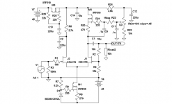
Not quite true even this one has a slight resemblance with the inputstage of an Aleph.
Anyway less problematic than the Zen-style pre I showed in the "2SK170 limit"-thread as Zin is high here.
Distortion will prove to be extremely low, well below 0,05% at 6V out at 6dB gain. Sims say 0,0006% but I wouldn´t count on that even if distortion figures for the other versions has proven right.
This one will also have a upper -3dB point that is many times higher than the Zen-style.
Clipping at over 13Vrms out into 10kohm.
We will just hope for that it sounds right.....
Attachments
Last edited:
Very Nice design! I like the Miller compensation you did with C2. Protects the transistor of excessive voltage swing too, I guess. Why did you choose active biasing instead of resistor bias? Apart from better noise rejection, does that help performance? I usually resistors bias because people say it sounds better, but who knows.
Last edited:
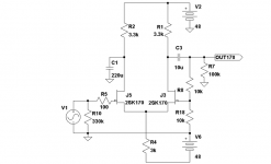
OK, it can be made all R. But due to the higher loading we will probably reach 0,1% THD at 6Vrms out into 10k. If we substitute the right drainresistor with a cheap Hammond 150H/8mA we are on track again. No we should get at least 11Vrms out at same THD as above with predominantly 2nd order overtones.
C1 in the first schematic is only for making the input resistor to behave like a SF.
C1 in the first schematic is only for making the input resistor to behave like a SF.
Attachments
Last edited:
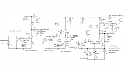
As this still is at the design-level I have done some side-by-side sims. This to get to know how FETs work having only used them as CCS´s before. Used two known and appreciated designs and adapted my circuit to one of them in terms of voltages and current. Can´t say I am dissapointed as this moment.
I am now only waiting for my 2SK170s, IRF610s and 2SK322s to arrive. Listening and measuring IRL still is king😉. Will first of all try the chokeloaded version mentioned above.
I am now only waiting for my 2SK170s, IRF610s and 2SK322s to arrive. Listening and measuring IRL still is king😉. Will first of all try the chokeloaded version mentioned above.
Attachments
C1 in the first schematic is only for making the input resistor to behave like a SF.
I was only commenting on C2 and that it provides a virtual ground at the drain of the input JFET. I guess you meant to say C2? C1 is just a coupling cap.
What does SF mean?
I've some BF862 JFETs and some IRF610s. Maybe I'll get one built first. 😉
Though, very highly unlikely since I'm loaded with projects right now. Got to get serious and finish a speaker build I'm working on.
I was only commenting on C2 and that it provides a virtual ground at the drain of the input JFET. I guess you meant to say C2? C1 is just a coupling cap.
C2 that I of course ment is just a de-coupling cap😉. About SF, it´s short for source-follower.
BF862 has in my opinion to low voltage capability for getting adequate overload margin, so 2SK170 or 2SK223 is what should be used.
Hi Lars,
the R15 in the middle circuit (post #5) should be 10R to 15R. With 100R the Id of that CCS will be too low.
the R15 in the middle circuit (post #5) should be 10R to 15R. With 100R the Id of that CCS will be too low.
Last edited:
...
BF862 has in my opinion to low voltage capability for getting adequate overload margin...
That's true, but I'd rather cascode the BF862 (when higher supply voltage needed) then use the k170 which is (IME) sonically inferior.
Hi Lars,
the R15 in the middle circuit (post #5) should be 10R to 15R. With 100R the Id of that CCS will be too low.
Hey Juma,
Adjusted Id for ca 12mA, at about the same current as the driver. Will probably not make so much difference sonically with higher current. Used the NXH model.
cascode the BF862
At what voltage would you bias the upper FET, with same voltage over both? Have one a few discouring theoretic examples with various gatevoltages at the upper FET. Don´t think I will build it but I am curious of the solution.
I don´t like them in the tube world where I have tried quite a few😉. Rod Coleman has a folded cascode concept, triode in the first and then a PNP BJT, that he says he likes.
Last edited:
10-15V Vds for gain device (with Id at 10-12mA) and the rest of the voltage on cascoding BJT (I prefer them - cheap, simple, works great)...At what voltage would you bias the upper FET, with same voltage over both? ...
Hey Juma,
Simmed the rightmost circuit from post#5 and added a BC547C as upper device with ca 10V over the FET.
Initially I was to try it at 48V but one have to add 10V as the upper device can´t swing below Vds.
Compared it against a 2SK170 at 48V and performance showed to the be on par or a tiny, tiny bit better for the cascode. The explanation to this is probably that the raw gain of the cascode is 6dB higher, so feedback is also 6dB higher.
But the FET seems to have lower distortion in itself as I suspected.
Hey Lars,
you seem to really enjoy the sims 😀
C'mon, it's a simple and cheap circuit, build it and tell us how does it sound - it's very intriguing and I would build it myself but I'm burried for next couple of weeks (building a circlotron with laterals)
you seem to really enjoy the sims 😀
C'mon, it's a simple and cheap circuit, build it and tell us how does it sound - it's very intriguing and I would build it myself but I'm burried for next couple of weeks (building a circlotron with laterals)


Hey Juma,
Anyone who makes the drawings first. Also simulations are done before whatever technical area you work with. After one has a few models it is time for soldersmoke and IRL tests😉.
Zen Mod,
Interesting contribution to this thread. Useful😉.
Anyone who makes the drawings first. Also simulations are done before whatever technical area you work with. After one has a few models it is time for soldersmoke and IRL tests😉.
Zen Mod,
Interesting contribution to this thread. Useful😉.
believe me - Juma is better when I'm on his back ........
lately I have less time for contributing - probably less energy for thinking .....
ask Juma - why .....
besides - we already beat to death some monkeys ......... in the past .....
lately I have less time for contributing - probably less energy for thinking .....
ask Juma - why .....
besides - we already beat to death some monkeys ......... in the past .....
Last edited:
Actually I have bag of sand on the way for testing some variations on this theme.
please - do that 😉
- Status
- Not open for further replies.
- Home
- Amplifiers
- Pass Labs
- Preamp with more Aleph than Zen-style