Hello,
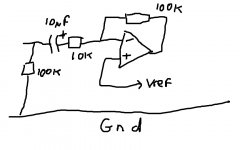
I've done an AUX in conversion for a LEXUS factory radio, however do to the limited output of my smartphones headphone jack the sound is too quiet. So I thought about making a preamp. I've got the basic understanding from this picture:
The op amp will be using a single power supply, 8v from inside the head unit, as I imagine it will be most stable in the car. The AUX cable is currently connected to the inside of the head unit, left and right channels to their points L+ and R+, and the ground is connected to the L- and R-, signal grounds. My question is, when I add the preamp, which ground should i use for the op amp supply, and where do I connect the AUX ground?
I've done an AUX in conversion for a LEXUS factory radio, however do to the limited output of my smartphones headphone jack the sound is too quiet. So I thought about making a preamp. I've got the basic understanding from this picture:
An externally hosted image should be here but it was not working when we last tested it.
The op amp will be using a single power supply, 8v from inside the head unit, as I imagine it will be most stable in the car. The AUX cable is currently connected to the inside of the head unit, left and right channels to their points L+ and R+, and the ground is connected to the L- and R-, signal grounds. My question is, when I add the preamp, which ground should i use for the op amp supply, and where do I connect the AUX ground?
You can use either ground L- or R-.
To make the circuit stable I would put 33pF across the 100K resistor.
The 741 bandwidth is 1MHz. This means with gain of 100 you will get audio bandwidth of 10KHz. Also the 741 is a very old op amp. Replace it with something like NE5532 or similar.
To make the circuit stable I would put 33pF across the 100K resistor.
The 741 bandwidth is 1MHz. This means with gain of 100 you will get audio bandwidth of 10KHz. Also the 741 is a very old op amp. Replace it with something like NE5532 or similar.
Thank you for your response. I won't be using 741, it's just an example. I can use the L- or R- for both the supply ground and the aux in?
Is that the actual circuit you'll use?
if so:
1)single +8V is about the lowest you can use with a 741 or any other standard Op Amp (TL071, etc.).
You might try to get a rail to rail one, which still is inexpensive (couple bucks) and is happy at such low voltages.
Read the proper datasheets.
2) that schematic is mono/single channel, but it looks like you are referring to a stereo unit, in that case use a dual Op Amp.
A TL072 will do, but as suggested earlier try to get another better suited to such low supply voltage.
3) the voltage divider (47k / 47k) to get 1/2 Vcc for biasing is fine , but the .1uF cap used for decoupling is way too small, use at least 10uF and preferrably 100uF.
4) that amp has way too much gain (100X) for the purpose intended , very low impedance (1k) and bass is murdered below 1600Hz because of the 100X too small series .1 uF
Use 10k or 22k input resistor for 10X or 5X gain and , say, 1uF input cap, positive towards Op Amp input.
5) ground is ground, meaning power supply ground or presumably L- and R- connections.
Check for continuity among all of them.
Last edited:
I won't be using the actual circuit, I used it as a base to gain an understanding of op amp amplification. I'll be using a NE5532, so a 8v supply will be alright with it. The gain will be 10x. L- and R- connections are connected with bypass capacitors in series to the audio processor in the head unit. L- and R- there's no continuity between them and the common ground, so they are isolated if I understand correctly? Your cap recommendations have been noted 😉
you have shown an inverting topology.
Are you sure that is what you need?
You have said you will change to a 5532. The MINIMUM supply voltage for that opamp is 10Vdc, Ti tells you so in the datasheet. And it is not rail to rail output.
It appears from your posts that you don't have a clue on what you are trying to achieve.
Post the circuit you intend to use.
8Vdc will limit your maximum output to ~2.5Vac if you use an opamp capable of operating from rails down to 5 or 6V and it is a rail to rail output stage.
With a gain of 4 times (+12dB), the maximum input would be around 650mVac
Any more and you will have gross distortion.
Last edited:
This is the circuit I drawn up. I haven't used op amps before, so the parameters are still a bit confusing to me. When I read the datasheet at first I immediately assumed that the minimal supply voltage is 5V... I want a gain of 10x, would this circuit work if I used a 12V supply?

Its basically fine. Your 10k input resistor defines the input impedance which means the coupling cap could do with being larger. Nothing wrong with an electrolytic here (say 10uf, with the plus end to the opamp). You should add a 100k from the open end of the cap to ground to define the potential at zero volts. That will stop thumps and bangs as you connect things to it.

The input caps were done right on the first drawing, not the second one. To the first drawing, connect the 100kΩ tack-down resistors between the input jack side of the coupling cap and ground. The input resistors R1 and R2 are set DC-wise by the op amp output, through the feedback resistor, so the right side of the cap will be biased to 1/2 Vcc; if you use an electrolytic input coupling cap (because it should probably be closer to 10µF and not 1µF), the R1 or R2 side will positive. As long as you have a single supply and R6 = R7, you will bias the amp properly, and you will get a bang upon startup - no avoiding that unless you use a bipolar supply. However, I bet that the radio will have some startup muting anyway, so it's likely to be a non-issue. And, with the tack down resistors, there should be no clicks when you connect/disconnect to the aux jack.
Maybe parallel a 10-20pF capacitor across R3 and R4 just to make sure the op amp remains stable, and also parallel a 0.1µF ceramic across C4 for similar reasons and you should be good.
Maybe parallel a 10-20pF capacitor across R3 and R4 just to make sure the op amp remains stable, and also parallel a 0.1µF ceramic across C4 for similar reasons and you should be good.
Thank you for your response. I have one more question. I'm doing this for a friend of mine, and he asked me to keep the CD function. The aux shares the connection with CD output, so it can only be used when there's no cds playing. I want to make the pre amp inside the head unit, thus it would always be powered on. If a CD is playing the CD signal would be on the op amps output, and I imagine that would be bad. Is there a way to make the op amps output flow in one direction? Or should I make a detection circuit for the aux to switch on the preamp only when needed?
you have shown an inverting topology.
Are you sure that is what you need?.........................
8Vdc will limit your maximum output to ~2.5Vac...................
You are still showing an inverting topology. I have to ask again: Is this what you NEED?This is the circuit I drawn up. I haven't used op amps before, so the parameters are still a bit confusing to me. When I read the datasheet at first I immediately assumed that the minimal supply voltage is 5V... I want a gain of 10x, would this circuit work if I used a 12V supply?
View attachment 519138
With a gain of 10times (+20dB) the MAXIMUM input signal will be around 250mVac. average levels from your source will be around a third to a tenth of this, i.e. 25mVac to 80mVac will be driving your amplifier into clipping.
Is this really what your friend NEEDS?
Something like this?
Like this.
Attachments
I have found that getting the headphone out level from portable music player devices to line level involves a voltage gain of around 3 to 5x. Too much gain in the preamp and you have to set the player's volume too low and can bring over more noise. Ideally you want the player's volume at around 2/3rds of full.
This way you can set the volume on the main amp to a reasonable level and not get blasted out of the room (car) when you switch to another source not to mention the noise from its amplifiers by having the volume set too high.
This way you can set the volume on the main amp to a reasonable level and not get blasted out of the room (car) when you switch to another source not to mention the noise from its amplifiers by having the volume set too high.
Using the recommendations in this thread, I redrawn the circuit, for non-inverting amplification and 5x gain. I read about this a bit, and swifted through a lot of circuits, some use input resistors some don't, is it mandatory? If so, how to determine what values should I use? And what about R12 and R13, I saw a few circuits using them, what's their use? Values seemed to me random.

The non inverting is a bit different. The two 100k's (value not critical but must be equal) bias the + input to half supply voltage, The gain is set by the 10k feedback resistor and the resistor that goes to ground via a cap. The cap maintains the DC conditions of the opamp. So for a gain of around 5 you could use a 2k2 resistor and say a 22uf cap.
This is the non inverting at its most basic... the bias part (the two 100k's) could usefully be modified to give a cleaner voltage. As it stands, any noise or supply disturbance will couple into the input.
This is the non inverting at its most basic... the bias part (the two 100k's) could usefully be modified to give a cleaner voltage. As it stands, any noise or supply disturbance will couple into the input.
Attachments

the gain of an inverting opamp is -Rupper/Rlower
The gain of a non-inverting opamp is +Rupper/Rlower +1
If you want 5times (+14dB) then Rupper/Rlower are selected to give either 5 for inverting or 4 for non inverting,
eg 10k/2k = 5times for inverting.
10k/2k5 +1 = 5times for non inverting.
The gain of a non-inverting opamp is +Rupper/Rlower +1
If you want 5times (+14dB) then Rupper/Rlower are selected to give either 5 for inverting or 4 for non inverting,
eg 10k/2k = 5times for inverting.
10k/2k5 +1 = 5times for non inverting.
I tested out the circuit mooly posted on a bench, with 12v single supply operation. And the output is quieter than the input. What might be the problem? The gain is set with a 10k and 2k2 resistor with a 22uf electrolytic cap. The gain should be about 5.5.
Last edited:

- Status
- Not open for further replies.
- Home
- Amplifiers
- Chip Amps
- preamp using an op amp