I have a 1993 Fender "The Twin" amp that sounds like pure garbage. I've messed with it here and there trying to figure it out and I've decided it's time to fix it.
It sounds like the speaker is blown but they aren't. I've used other heads through them and they sound great. It only happens through the dirty channel and becomes more pronounced as I increase the preamp gain.
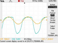
I prodded around with a scope to see if I could find the issue. I think I did. See attached image.
I used a signal generator set to ~95Hz. That's roughly a low F# (2nd Fret low E string) because I would always hear the problematic sound really well on that note. I set it to 1V peak-peak which is roughly the output of my SG.
What you're looking at: CH1 (orage signal) is the input from the guitar as measured on pin 2 of V1. This is the 1Vp-p from the signal generator. CH2 (blue signal) is the signal going into pin 2 of V2. So it represent the change in signal due to the second gain stage which is the second half of V1.
I have the gain cranked and as you can see the top half of the signal is clamped at 5V while the bottom half goes to -15V. (Notice that the volts per division is different for the different channels. 5V per division for CH2. 500mv per division for CH1.)
The gain stage in question is the second half of a 12ax7 and it's plate resistor is 100K and cathod is 2.7k with a plate voltage of 225V.
What I've done so far:
Any ideas why this would go so asymmetrical? It's like that tube isn't conducting equally across the whole range of operation but I know it's not the tube.
It sounds like the speaker is blown but they aren't. I've used other heads through them and they sound great. It only happens through the dirty channel and becomes more pronounced as I increase the preamp gain.
I prodded around with a scope to see if I could find the issue. I think I did. See attached image.
I used a signal generator set to ~95Hz. That's roughly a low F# (2nd Fret low E string) because I would always hear the problematic sound really well on that note. I set it to 1V peak-peak which is roughly the output of my SG.
What you're looking at: CH1 (orage signal) is the input from the guitar as measured on pin 2 of V1. This is the 1Vp-p from the signal generator. CH2 (blue signal) is the signal going into pin 2 of V2. So it represent the change in signal due to the second gain stage which is the second half of V1.
I have the gain cranked and as you can see the top half of the signal is clamped at 5V while the bottom half goes to -15V. (Notice that the volts per division is different for the different channels. 5V per division for CH2. 500mv per division for CH1.)
The gain stage in question is the second half of a 12ax7 and it's plate resistor is 100K and cathod is 2.7k with a plate voltage of 225V.
What I've done so far:
- Re-tubed it. Tried multiple (known to be good) V1 tubes.
- Checked B+ and tube voltages (Slight variation from what schematic indicates they should be but nothing crazy).
- Checked the plate and cathode resistors.
- Prodded around with a scope and found this weirdness.
Any ideas why this would go so asymmetrical? It's like that tube isn't conducting equally across the whole range of operation but I know it's not the tube.
Attachments
http://ampwares.com/schematics/the_twin.pdf I believe this is the correct schematic. There are a lot of components between V1 pin 2 and V2 pin 2 so you are going to have to go step by step. Start at V1 pin 1 (plate of triode 1) and see if the signal looks ok. Then check V1 pin 7. Then V1 pin 6. And so on to isolate where the problem begins.
Hi, A bit out of the things I work with normally (hi-fi amps etc). I would look at the portion of the circuit that includes the LED/resistor assembly. If the LED isn't getting the proper voltages to turn it on, basically a bias level, it can cause serious distortion in the circuit it is controlling.
Does the signal clean up at lower input levels?
Does the signal clean up at lower input levels?
OK, jerluwoo. That is the correct schematic. It's the one Fender sent me a copy of based on the serial number of the amp so we're all on the same page. Theirs is more clear so I'll post it here because we're going to need to see the detail.
Anyway, I knew what I had to do but I was being lazy hoping someone had seen this before. You gave me the motivation to actually get in there and figure it out. So thanks. Here we go.
Screw Up: I made images for every one of the following test points and none of them turned out right. They were all the same blank screen. Not sure what's going on there. This is the first time I've used this feature on my scope and it seemed to work so well for the first one. Anyway, I'll describe my findings.
I tested the following points.
V1 Pin 7: All good here. I started here in hopes that I could isolate the issue to the circuitry between V1 Pin 6 and V2 Pin 2 and eliminate the need to check all throught he tone stack. I got lucky because the signal here was pristine and so I'm assuming the circuit is good up to this point.
V1 Pin 8: It starts. It's very minor but there is definitely some asymmetry starting here. Also a phase shift but I assume that's because of the network of caps in parallel with the cathode resistor.
V1 Pin 6: I'm in the signal chain at this point and I'm going to go point by point all the way to V2 Pin 2. Very minor asymmetry here. About the same as Pin 8 but no shift. I couldn't crank the gain here because the peak voltage was approaching 300V and my scope is only rated for 300V. I went to about 9 out of 10 on the gain and noted that asymmetry was definitely present.
Between R35 & R36: Back in DC-blocking land so gain is back to 10. Asymmetry picked up substantially here.
Between R36 & R37: Major asymmetry. As bad if not worse than V2 Pin 2 from my first post.
C21 to Ground: -2.4V with just a little fuzz. No real change based on position of the gain knob. I'm not sure what should be expected here but I feel like this is wrong.
Wiper of R38: This is the middle leg of the half of the gain pot that lives in this part of the circuit. It's a dual pot as can be seen on the schematic and they appear to use it to roll off some highs as the gain increases. This test was an anomaly which prompted me to look further into the gain pot. This is where I'd like to get some opinions.
The schematic shows which direction the wiper is supposed to go when you turn it clockwise. Accordingly, R38 should become a short as you turn it all the way clockwise (max gain) but that isn't what is happening. When I turn it all the way clockwise the resistance between R40 and C21 becomes 1Meg. The other half of this dual pot works as indicated by the schematic. I looked closer and it appears this pot was replaced by a previous owner because it isn't the same style as all the others. It can't just be rewired because it's pcb mount. The traces already dictate how it has to operate.
Now the big question. Consider the operation of this circuit in it's current state. When the gain is maxed, maximum signal gets through but the secondary portion of that pot is at maximum resistance instead of a short as it was intended. Would anyone expect that to cause the signal to be so asymmetric?
My thought is to order the correct pot and install it, clearly. But beyond that, C21 is causing me some headache. Should it behave the way it does? Setting at -2.4V? I'm thinking about replacing C21 and C20 as well just in case.
Would love to hear your thoughts. Thanks.
Since this is a PCB amp, the previous job could have only made a partially good solder joint as soldering on these is trickier. I had the same problem come to me. I found that the owner tried to fix it himself and didn't make good contact with the trace. It worked for a while but after time,it failed.
The asymetrical clipping is actually what is to be expected with valve amps.
When the grid gets positive wrt the cathode, it starts to conduct current.
Since the preceding gain stage can't supply much current, the signal clips, but only on the positive swing. Soft clipping on one side translates as 2nd harmonic.
Swinging more negative does nothing in terms of grid current, so no clipping there. The triode is driven into cutoff, so you will see clipping on the anode (phase inverted, so on the positive swing where the anode cannot go higher than the supply voltage).
About the voltage on C21, without signal, does it sit at 0Vdc?
I suggest your input signal is much too hot for troubleshooting. Your Fender schematic gives anode voltages and signal levels right thro the signal chain for a 100mV input. Comparing these against those on your amp with the same input level might be a good place to start.
Good luck.
Good luck.
I suggest your input signal is much too hot for troubleshooting. Your Fender schematic gives anode voltages and signal levels right thro the signal chain for a 100mV input. Comparing these against those on your amp with the same input level might be a good place to start.
Good luck.
Thanks for the advice. I'm going to try lowering it and looking for something else. Where does it indicate that they use a 100mV signal?
The asymetrical clipping is actually what is to be expected with valve amps.
I was aware that valve amps have asymmetrical clipping but I didn't know it was this drastic. I checked the plate voltage of V1b, V2a, and V2b and then checked the signal level after the coupling caps for each one. Adding the positive magnitude of the signal to the plate voltage resulted in the B+ voltage for that stage so it is truly going as high as it can. This likely means its behaving appropriately in this respect. But I still didn't expect it to go so low. In some cases the magnitude of the lower half of the signal is large multiples of the upper. 3 to 1, 4 to 1, etc.. Is this much asymmetry expected?
Further, this still leaves the terrible sound. Any tips on how to track down an undesirable sound by looking at the signal?
Sorry. Misread note 6 (old eyes...doh).
I would expect an input of 10mV at pin 2 for 620mV at pin 2 from most 12AX7's with those anode and cathode resistor values.
Note they tested at 1kHz.
Cheers
JimG
I would expect an input of 10mV at pin 2 for 620mV at pin 2 from most 12AX7's with those anode and cathode resistor values.
Note they tested at 1kHz.
Cheers
JimG
I was aware that valve amps have asymmetrical clipping but I didn't know it was this drastic.
Overall symmetry vs. asymmetry is mostly about bias points and relative signal levels. Compentent amp designers are well aware of shaping this clipping characteristic by varying bias points or overall signal levels within the gain stages. "Gain staging" as it's called...
Take a generic common cathode amplifier gain stage. You can bias it so that its plate is about 1/2 of B+, which provides equal headroom for voltage swing in both negative and positive halfwaves. Or you can bias the stage so that plate voltage is either closer to B+ or closer to zero, which increases headroom of voltage swing on one halfwave while decreasing it on the other. The further the bias shifts from "center" the more prominent the asymmetry becomes. Most tube gain stages are deliberately biased for asymmetric headroom, therefore also asymmetric clipping distortion. As said, symmetric clipping is largely just a matter of rebias.
Then there's aforementioned clipping due grid conduction. It's caused by too high grid vs. cathode voltage difference so whether it gets designed in or not is largely an issue of tube bias (again) and signal levels hitting the grid. Again totally avoidable by design but often on the contrary "designed" in to enhance asymmetric characteristics. Competent amp designers are well aware that they can shape grid clipping characteristics, not only by varying source impedance and current amplifying capability of the driving stage, but also by choosing something between capacitively bypassed cathodes with low Rk's vs. non-bypassed cathodes with higher Rk's. If you look at high gain guitar preamp designs you often see that there's a lot going on in this regard.
Naturally, the more you overdrive the gain stages or grids (or wherever clipping happens) the more pronounced the symmetry vs. asymmetry gets. This characteristic is of course largely a matter of establishing the preferred overall signal levels within various stages of the circuit.
The only means in which asymmetry is inherent to tubes can be observed from the characteristic curves, which often portray different knee characteristics in transition regions to cutoff or saturation. One tends to be soft transition, the other is hard.
Last edited:
Wow, teemuk. That was a great explanation. Looking at the B+ vs bias points of each of these, it's pretty clear that there will have to be asymmetry once you start bringing the gain in because it's biased much closer to B+ than zero. Thanks. I'm starting to explore other possibilities with this amp.
- Status
- Not open for further replies.
- Home
- Live Sound
- Instruments and Amps
- Preamp stage is going very asymmetrical. Why?