How about a link or an actual attachment?See my gallery. It is the circuit i usee in my Mezmerise, that you helped me with so much.
Calvin, thank you very much for your suggestion, I am now weighing up the choices, this a long-term project 🙂
I am looking for a simple-to-use (and also free) schematic drawing package, please tell me what you use, and is it free?
I am looking for a simple-to-use (and also free) schematic drawing package, please tell me what you use, and is it free?
Last edited:
search in google image '4013 toggle switch circuit'
Gajanan Phadte
that is helpful thank you.
Ted
Hi,
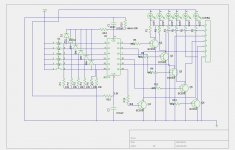
here´s a 4-in-1-out switch with an additional optional output relay.
It uses a 4-in BCD-to-decimal decoder CD4028.
From this decoder it uses only the single-bit outputs 1,2,4 and 8.
Diodes D1-D4 feed the output condition back to the associated input to achieve a latched, self-holding condition.
The 4 outputs feed into a NPN transistor-Array that drive the relays and LEDs.
The optional C1 realizes a preset condition and decides which input is chosen after power-up ... in this case Input No.1.
If another one of the input tactile switches is closed, the decoder momentarily sees two inputs active and switches from the former output to the new output (which is anything different from 1,2,4 or 8).
As now there´s no feedback from output to input any more, only the (still) pressed switch is seen as new input.
The decoder switches to the corresponding output (1,2,4 or 8) which is then latched again.
The switching action is "break before make".
D5-D10 collect the unused outputs, of which one is momentarily active when a new input switch is pressed.
This pulse is used to trigger one half of a Dual Monostable Multivibrator CD4098.
Every pulse at its input triggers the CD4098 output for a certain delay time, that depends on R5/C2.
The "Out"-relay falls off for a period spanning the delay time.
After the delay has passed the "Out"-relay releases the output again.
The amount of parts depends on wether or not the Out-option is used.
Without the option IC1, 4 Diodes and 4 NPN-transistors suffice.
jauu
Calvin
Hi,
This circuit is what I'm looking for (post #20). One disadvantage is that it is 'break before make'. I was wondering if I could adjust it to 'make before break'. This with an extra diode and cap at the input of the ULN2804. As the input of this driver is pulling only a tiny current, the output stays longer "active" when de-activated. As the 4028 can deliver more current than the 2804 is pulling, the next selected input will be active before the last one will de-activated I would think.
Anybody an idea whether this could work? See modified circuit below.
Regards
Attachments

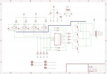
simpl, but working 4 input driver circuit
Hi guys. Here is the schematic of my driver circuit, which is simple, effective and cheap...only the relays not showed, because they have independent board. Relay`s type is Takamisawa RY12W-K. Relay board and thsi driver board connected via wires....
Hi guys. Here is the schematic of my driver circuit, which is simple, effective and cheap...only the relays not showed, because they have independent board. Relay`s type is Takamisawa RY12W-K. Relay board and thsi driver board connected via wires....
Attachments
- Home
- Source & Line
- Analog Line Level
- preamp relay driver needed