I've undertaken a rebuild of a completely screwed up, commercial preamp for a friend of mine. By "completely screwed up" I mean mutilated by a solder happy modder or two. It looked like the last guy that played with it couldn't get it to work, so he just routed the line stage input to the output and gave it back to my friend!
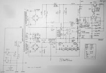
Anyway, I've gotten the amp circuit back to where it needs to be, but now there is a hum problem...lots of hum. What we have is a regulated supply, but I'm not all that familiar with these things. I'm guessing that U1 is an error amplifier (the negative input is at a reference DC while the positive input has some B+ ripple injected into it through C17) controlling Q1 which works as a (shunt?) regulator. Again, that's a guess. I'm a complete novice when it comes to regulators.
It appears that U1 and U2 may have been "upgraded" to OPA604 and AD711, respectively. If calibration is important maybe this is why it no longer nulls the hum? B+1 has 5mV of hum which is way too much for the two(!) gain stages it feeds. There ends up being 5mV hum on the final stage's output. I suspect the regulator circuit around U1 is not working and/or adjusted properly. B+2 (supplies the phono section) seems OK for now, but it's hard to tell with all the hum from the line stage.
The voltages on U1 seem OK. 24V on pin 7, 0V on pin 4. I can't measure pin 2 without affecting the measurement because it's set through such a high impedance voltage divider. It is close to the 12V it should be.
It's not a ground loop. Clipping in a 470uF cap across C14 reduces the hum by 2/3. I could just do this, but I'd prefer to have it working properly and as original.
Could someone offer some advice on how to proceed?
Thanks in advance.
Attachments
A trick to measuring the inputs of the opamp: rather than measure voltage to ground, measure the voltage from inverting to noninverting input. If it's zero, the opamp is working. If it's 0.7, then one of those protection diodes is turned on.
In any case, it's difficult for me to read the values on this little screen, but it appears that U1 and (I think it says) Q1 exist to draw a current through the Zener which provides a floating supply for U2. U2 is the error amp driving the Darlington pass devices.
Important question: what is the frequency of the hum? 50 or 100?
Get rid of the new opamps and go back to the originals. Check differential voltages to make sure they're zero and that the inputs are sitting somewhere between the opamp supply voltages. Make sure all the transistors are turned on.
I'm going to take a WAG that you've got a ground loop, despite what you've concluded. 5mV of ripple on a line stage B+ is not an enormous amount- certainly not enough to cause massive hum.
"I'm going to take a WAG that you've got a ground loop, despite what you've concluded. 5mV of ripple on a line stage B+ is not an enormous amount- certainly not enough to cause massive hum."
I agree with SY. 5mv isn't that much ripple.
I would replace the power supply electrolytics if the power supply hasn't been powered up for a while.
I agree with SY. 5mv isn't that much ripple.
I would replace the power supply electrolytics if the power supply hasn't been powered up for a while.
SY said:I'm going to take a WAG that you've got a ground loop, despite what you've concluded. 5mV of ripple on a line stage B+ is not an enormous amount- certainly not enough to cause massive hum.
Thanks for the response.
The hum frequency is certainly 100Hz. I'd guess the level to be 100mV or so at the speakers.
Regarding the ground loop - I don't think so - at least not an external one. It hums with no other gear connected. I have a photograph of an unmodified example and I've grounded the input / output wiring as in the photo - the rest of the layout is all on the PCB.
5mV is a lot of ripple when you're feeding two cascaded 6DJ8 stages with it that's then going to be amplified another 20 times or so with a power amp, isn't it? Some of the gain is thrown away with unbypassed cathode resistors and a feedback loop from the plate of the second triode back to the cathode of the first.
Removing the first triode reduces the output hum from 5mV (coincidentally the same figure as the supply ripple) to 1mV. I would think that an acceptable level of output hum in a commercial preamp would be 0.1mV or less.
I measured the inputs of U1 and U2 as suggested. There is about 130mV of DC between the + and - input of U1 (there is also some AC but I figure that's supposed to be) but I still think my multimeter is affecting the measurement. The - input voltage is set by two 10M resistors which is close to the input impedance of my multimeter. Still if it were 0V as you say it should be, there would be no current flowing to upset the measurement so something's amiss.
There is 0mV DC measured between the inputs of U2.
So can you say with certainty that B+1 is unregulated? I can't see how 100uF - 4K - 2uF is adequate smoothing for two cascaded gain stages even at low current.
Another thing I've noticed is that the hum falls as the amp warms up. It starts at 8 or 9mV and falls to 5mV after 10 minutes or so. Maybe the caps are dodgy?
B+1 is definitely unregulated.
It's easy (too easy) to have an internal ground loop. When you removed the tube and saw a reduction in output hum to 1mV, what happened to the power supply ripple?
If you've got a spare e-lytic hanging around, it wouldn't hurt to try to replace C14. But that's less likely the culprit, I think.
Are the gain tubes cascodes? If not, 5mV of supply ripple is not excessive.
Bon chance!
SY said:It's easy (too easy) to have an internal ground loop. When you removed the tube and saw a reduction in output hum to 1mV, what happened to the power supply ripple?
The power supply ripple dropped when the tube was removed - presumably due to the lower current draw from the power supply.
SY said:If you've got a spare e-lytic hanging around, it wouldn't hurt to try to replace C14. But that's less likely the culprit, I think.
I paralleled a 470uf cap across C14 and the hum dropped substantially, but not enough.
SY said:Are the gain tubes cascodes? If not, 5mV of supply ripple is not excessive.
No they are just grounded cathode stages. I thought that the high effective plate resistance of a triode stage with an unbypassed cathode resistor would cause the loss of much of it's ripple rejection capabilities. The first stage has a 300K plate resistor and an unbypassed 11K cathode resistor. Wont more than half the supply ripple appear on the plate because the resistance of the tube + cathode resistor is over 300K? I guess the local feedback might act to reduce it somewhat, but how much?
Tekko said:This thread belongs in the Solid State department.
I suppose it does technically speaking - but look at the supply voltages. It's a tube preamp.
Try actually replacing C14, not just paralleling it.
If you can sketch out what's going on with the grounds, that could prove helpful.
What's the annotation on R38? And on R42? Do you see ripple on the collector of Q1?
If you can sketch out what's going on with the grounds, that could prove helpful.
What's the annotation on R38? And on R42? Do you see ripple on the collector of Q1?
SY said:Try actually replacing C14, not just paralleling it.
If you can sketch out what's going on with the grounds, that could prove helpful.
What's the annotation on R38? And on R42? Do you see ripple on the collector of Q1?
Thanks for persisting with me, SY. 🙂
R38 = 4.99K 1% or 5.23K 1% to match graded regulator
R42 = 7.5K 5% 10W WW
Q1 Collector has approx 1V of ripple.
I'll try replacing the cap later today.
Ground layout will be forthcoming as well.
There is about 130mV of DC between the + and - input of U1 (there is also some AC but I figure that's supposed to be) but I still think my multimeter is affecting the measurement.
I missed that before. What's the voltage on the output of U1?
SY said:What's the voltage on the output of U1?
U1 DC output = 6.7 V
U1 AC output = 0.9 mV
SY said:Let's see those grounds!
Here are photos of the top and bottom of the circuit boards.
Top:
http://members.iinet.net.au/~jmai/pix 441.jpg
The red and blue twisted wires are signal and ground to the RCA output jacks which are isolated from the chassis and are not grounded anywhere else. (There is a muting circuit attached to the signal at the RCA jacks.)
Bottom:
http://members.iinet.net.au/~jmai/pix 443.jpg
You can see the ground plane for the power supply extends to the connections for the RCA jack grounds just in front of the transformer.
Safety earth is attached to the chassis and the circuit ground on the input side of the circuit near the RCA jacks. I'll try to post more pictures showing how this is done.
The wiring through the center is for the regulated DC filament string. The last 6DJ8 in the line stage is AC heated, biased up to 24Vdc through two 100 ohm resistors forming a center tap.
OK, the voltage at the base of Q1 is not unreasonable.
A 6DJ8 in grounded cathode with a 300K plate resistor and an 11K cathode resistor? That's... beyond odd. I keep coming back to the fact that 5mV of ripple is causing untoward noise; with more normal ways of operating a 6DJ8, that noise will get knocked down by a factor of ten. Maybe the ripple isn't the issue...
Have you tried silly stuff like rerouting the output twisted pair? I notice that it runs right by some major hum sources. How are the RCA jacks grounded? Is the blue wire connected on both ends?
SY said:A 6DJ8 in grounded cathode with a 300K plate resistor and an 11K cathode resistor? That's... beyond odd. I keep coming back to the fact that 5mV of ripple is causing untoward noise; with more normal ways of operating a 6DJ8, that noise will get knocked down by a factor of ten. Maybe the ripple isn't the issue...
It looks odd to me, too, but there it is on the schematic. All the voltages indicated on the schematic are what I'm getting in the amp, so I'm pretty certain I haven't misread anything.
The line stage has a stupid amount of gain.
SY said:Have you tried silly stuff like rerouting the output twisted pair? I notice that it runs right by some major hum sources. How are the RCA jacks grounded? Is the blue wire connected on both ends?
I've tried moving the twisted pair around but the hum level doesn't change on the meter.
The RCA jacks are grounded through those blue wires and only those blue wires. They are connected at both ends.
SY said:So they're isolated from the chassis?
Yup! I can see the isolation washers on both sides.
One more thing- since this preamp has been in the hands of a modkateer, look around for any wires that may have been replaced, not just in the power supply but in the signal circuitry. In a gung-ho effort to make sure all the wires are Approved Audiophile Grade, an enthusiastic but ignorant modder (and that describes 99% of them) may have added a ground that wasn't there before or moved one to a spot that's "just as good."
Do you have a schematic for the line stage?
Do you have a schematic for the line stage?
- Status
- Not open for further replies.
- Home
- Amplifiers
- Tubes / Valves
- Preamp rebuild - hum problem