Hi, my opamp based preamp has a regulated power supply and draws in the neighborhood of 20mA total (no load, load = ?? have not gotten that far yet...) from the wall. Apparently this is not enough to draw down the 20 VA power transformer, which is 12VCT but creates + and - 20VDC. The problem is that the initial bank of filter caps (4400 uF per side total) feed a pair of Linear Technologies regulators which are spec'd for 20VDC maximum on the input, so I'd really like a little wiggle room to get the input voltage down from 20 VDC to 16 VDC or so.
Inserting a 750 ohm 3 watt resistor (one of those panasonic blue ones left over from a Pass project) in-line with the wall AC at one AC input of the transformer does the trick, reducing the AC from the wall by about 16 V and thus the DC from the filter caps by about 4 volts, dissipating about 0.34 watts as heat.
I would think this also reduces AC noise by the same proportion, a good thing. The LT regulators now get 16 VDC and output about 12VDC which makes them very happy.
Any problem with doing this?
you could also try the LM7815 / LM7915 1.5 amp voltage regulators from national, the input to this regulator needs to be between 17.5 VDC and 30 VDC which sounds like right in your area. I am not sure if putting a resistor in series with the line voltage is the best idea, but i will leave that up to someone else to answer who has a bit more mains voltage knowledge then me.
Dave
Dave
drummer_Dave said:you could also try the LM7815 / LM7915 1.5 amp voltage regulators from national, the input to this regulator needs to be between 17.5 VDC and 30 VDC which sounds like right in your area. I am not sure if putting a resistor in series with the line voltage is the best idea, but i will leave that up to someone else to answer who has a bit more mains voltage knowledge then me.
Dave
Right, those would work but I've already designed, ordered and stuffed my own PCB for these particular ultra low noise surface mount LT 1962/1964 regulators and it works great.
I could add in a 2nd "pre" regulation stage to feed the LT regulators but the problem with that is that (1) it would add noise using lower performance regulators, and (2) I would be compelled to use 15V fixed TO-3 regulators because the chassis is already cut for them and it would look super-cool.
I guess the issue with adding a resistor is the impedance of the AC line goes way up, but not sure if this is a real world problem given the tiny power requirements and relatively large filter caps.
Other than the 4400 uF per rail previously mentioned, each opamp has a pair of local 22uF caps right next to it and the regulators themselves feed a 220 uF cap on their output.
Hi,
you could split your filter bank and use an RCRC supply.
Adjust the Rs to get the highest voltage you can tolerate at the lowest output current and highest mains supply voltage.
You could also add a Zener or shunt regulator after the first and/or last R to pull the voltage down.
I do not like your idea of fiddling with the mains side.
Seems like an accident waiting to happen.
Hi lgreen,
I agree with Andrew, I'm not too fond of resistors on the mains side. What would be nice is a series resistance on each DC rail. This would be followed by a capacitor, giving you a C-R-C design. This allows you to use your low noise regs and enhances the high frequency attenuation from your supply (a good thing). Use the most inductive resistors you can lay your hands on! 😀
Reducing the input capacitance would also be a good thing. Do you know how short a conduction angle you must have now?? That's RFI central. Some ripple would be preferable in the first stage because your second stage will smooth it out and your regulators will have an easier time with that then the high frequency bursts from your original design.
What do you think?
-Chris
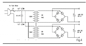
Ok guys, I got the idea of using the R's in-line with the AC from the Pass Labs Pearl Phono that I just finished. See attachement, it uses a 4.7 ohmer in each AC leg, and I'm just using one and making it bigger, no?
I'm not worried about saftey as it is well insulated from prying fingers.
Come to think of it, I forgot that the regulator board has a set of 1000 uF caps on the front end input so it would be easy to mod this thing for a CRC supply to feed the regulator. I'd use C=4400 (bridge board) R = 200 and C=1000 (reg board). This should give me a drop of about 4 volts at 20 mA load.
Anyway, thanks for mentioning the conduction angle and the RF, I am a little worried about the RF , i'm gonna have a lookie see and check it out. Appreciate the comments and you spending time on my posts.
other comments appreciated...
Attachments
If you have several filter caps in parallel, modifying the supply for a RCRC (note R at the start!) is a good idea, assuming there is always some load curren (say, a LED indicator...), to produce a voltage drop. The R at the beginning (before first cap) will widen the conduction angle and also smothen the ripple current, leading to a rather drastic reduction in RFI, at next to no cost.
You could also insert a diode string or even a low voltage zener in series with either supply, but honestly, I'd consider this a crutch. If it was me, I'd probably be winding anti-series windings on the transformer, before I'd go putting diodes or zeners in series...
If everytihing else fails, you have another possibility - put a cap in series with the transformer primary. Essentially, it's a non-ohmic voltage drop, but this technique is generally OK only for approximately constant current demand, and also, it needs to be additionally snubbered to prevent resonance with the transformer inductances (so, in practsie, a scope is required). Considering you have a relatively small conduction angle rectifier on the secondary, the current waveform is bound to hit the resonance(s) with one/some of it's harmonic/s so a snubber resistor (or better) is a necessity.
BTW a resistor in the primary side (assuming you are carefull to make it touch-safe) is not that unusual, and in fact looks like a correspondingly reduced resistance from the secondary side. The bonus is that it lowers inrush current at power on, and also acts as that first 'R' in the RCRC I mentioned above, so increases the conduction angle. It is even possible to use it as part of a filter by putting a series R-C across the transformer secondary - in essence, you make a Zobel network to compensate for the primary resistor and leakage inductance of the transformer. It helps greatly with diode switching transients, but needs measuring and/or modeling to get right.
Hi lgreen,
I agree with ilimzn (see my sig line though). I'd prefer a much more controllable R as a drop also in your secondary. The R-C-R-C is one of my favorites as you take the edge off the charging current. Your caps run cooler and so would your transformer.
-Chris 😉
That's silly overkill and a complete waste. If you reduce this to 1,000 uF (2,200 uF max) you will have a cleaner supply.I'd use C=4400 (bridge board)
I agree with ilimzn (see my sig line though). I'd prefer a much more controllable R as a drop also in your secondary. The R-C-R-C is one of my favorites as you take the edge off the charging current. Your caps run cooler and so would your transformer.
-Chris 😉
ilimzn said:If you have several filter caps in parallel, modifying the supply for a RCRC (note R at the start!) is a good idea, assuming there is always some load curren (say, a LED indicator...),
****
BTW a resistor in the primary side (assuming you are carefull to make it touch-safe) is not that unusual, and in fact looks like a correspondingly reduced resistance from the secondary side. The bonus is that it lowers inrush current at power on, and also acts as that first 'R' in the RCRC I mentioned above, so increases the conduction angle. It is even possible to use it as part of a filter by putting a series R-C across the transformer secondary - in essence, you make a Zobel network to compensate for the primary resistor and leakage inductance of the transformer. It helps greatly with diode switching transients, but needs measuring and/or modeling to get right.
oh there's gonna be some LEDs, let me assure you of that!
Thanks for the explanation you guys know your stuff! I tried a CRC and it works just fine with a 47 ohm power resistor, drops 2.8 volts. May try a RCRC with two 20's to see how that works.
Hi lgreen,
-Chris
Cool! Great news. Now you will have a low noise supply as long as you get the grounding right. 🙂I tried a CRC and it works just fine with a 47 ohm power resistor, drops 2.8 volts. May try a RCRC with two 20's to see how that works.
-Chris
Hi lgreen,
-Chris
Well, there is a difference between working, and working to the best it can from a noise perspective. You are using low noise regulators so naturally grounding will come up.If by "grounding right" you mean that the thing works, then all right!
-Chris
grounding
here is a question-
- this has a bunch of balanced inputs and outputs, do I connect the grounds of all of them to each other at the rear panel or just some? other option is to wire them to the boards for each channel
here is a question-
- this has a bunch of balanced inputs and outputs, do I connect the grounds of all of them to each other at the rear panel or just some? other option is to wire them to the boards for each channel
Hi lgreen,
I think you are getting ahead of yourself a little. Left them the way they were for now. Once the amp is working you can start changing things.
-Chris
I think you are getting ahead of yourself a little. Left them the way they were for now. Once the amp is working you can start changing things.
-Chris
anatech said:Hi lgreen,
I think you are getting ahead of yourself a little. Left them the way they were for now. Once the amp is working you can start changing things.
-Chris
Well Chris they are not connected yet! Everything is working and I just need to connect up the XLR and RCA connectors.
I typically connect all the grounds at the rear panel connectors, and run a wire from ONE of them to the signal ground.
Is this ok or should I do something else?
Hi lgreen,
If anyone has any better ideas, please feel free to interject here. I can't see the physical beast - so there is some guesswork on my part.
-Chris
Sorry about that. I normally work with things that stopped working and were hooked up.Well Chris they are not connected yet!
I would suggest running all the input grounds together and connecting to the input selector and on to the input ground of the PCB. Then tie the output grounds together and run those to the signal ground star where you head off to the main ground star.I typically connect all the grounds at the rear panel connectors, and run a wire from ONE of them to the signal ground.
If anyone has any better ideas, please feel free to interject here. I can't see the physical beast - so there is some guesswork on my part.
-Chris
anatech said:Hi lgreen,
***
I can't see the physical beast - so there is some guesswork on my part.
***
-Chris
Beast is one way to put it! Lots of wires going every which way just like always. OK, thanks for your help. I am working on the beast today so perhaps soon i'll post a pic.
- Status
- Not open for further replies.
- Home
- Amplifiers
- Solid State
- Preamp PS has too high a voltage- insert R?