I'm not sure where you are up to with all this but the proper way to do this is to have the relay as a normally closed short across the preamp output. It only opens after the switch on delay has completed and it should be arranged to close as near instantly as possible on power off. The opamps are short circuit proof. The only proviso is that you need a small series resistor (say 47 ohm) in series with the output to allow the feedback to be able to stabilise the DC conditions.
I'm just having a play around with a few ideas at the moment.
I'm trying the circuit I linked in post 16. Relay open with power off; Short delay at power up; fairly instant (hopefully) relay open on power off.
With the relay open, the output of pre is shorted to ground through a 47k resistor.
It's not built yet, but I will hopefully be able to trial it using an external psu.
I'm not sure where you are up to with all this but the proper way to do this is to have the relay as a normally closed short across the preamp output. It only opens after the switch on delay has completed and it should be arranged to close as near instantly as possible on power off. The opamps are short circuit proof. The only proviso is that you need a small series resistor (say 47 ohm) in series with the output to allow the feedback to be able to stabilise the DC conditions.
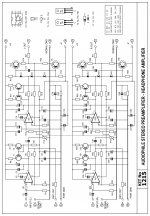
https://www.quasarelectronics.co.uk/kit-files/smart-kit/1215.pdf
i would hazard 47 ohms would not be enough.
i'd go for 1K ohm.
and it is good to go.
1k is a bit high as an output impedance figure. I'm assuming the preamp output is DC coupled too, if not then that problem is removed. A typical opamp should allow at least a 1 volt to be developed across a 47 ohm... I would have thought that enough to allow it to stabilise but as ever its one to try. If 47 ohm works then try 39 or 33 and check it still works. If it does then 47 ohm is fine, if not then 47 is marginal and should be increased to the next value up.
according to the schematic the output device is not the opamp.
hence i would not go for a low value like 47 ohm.
the thing states minimum 600 ohm load.
1K ohm would be good enough. (from safety perspective, surely not harm the output transistors. check the schematics in the link.
https://www.quasarelectronics.co.uk/...t-kit/1215.pdf
hence i would not go for a low value like 47 ohm.
the thing states minimum 600 ohm load.
1K ohm would be good enough. (from safety perspective, surely not harm the output transistors. check the schematics in the link.
https://www.quasarelectronics.co.uk/...t-kit/1215.pdf
Fair enough 🙂 I didn't realise it was a discrete output stage. Probably one where you would want to scope the output and see what actually happens amplitude wise at switch on and base a solution on the result. AC coupling (and then shorting) might be one approach if a high output impedance was a worry. Or just trust to not having issues with a series relay.
I had a quick scope of the output earlier, and although it wasn't particularly conclusive it seems like a burst of DC at the output on switch off.
I had a quick scope of the output earlier, and although it wasn't particularly conclusive it seems like a burst of DC at the output on switch off.
So... adding a relay that shorts the output shouldn't be a problem as far as power off goes.
On power on, I see there are those series output resistors... hmmm... and so I'm going to go back to what I mentioned at the start and say that I still think there would be no issue with the circuit stabilising. The stage has plenty of current capability (much more so than an opamp) and should virtually instantly settle to zero volts.
I would try it...... with the proviso that the output resistor is 47 ohms or higher.
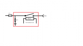
That's fine. Only downside with the series connection is the audio now passes through a mechanical contact and so the relay needs to be a type designed for low level signal handling. The 47k is not needed. It does nothing.
wrong, the 47K is needed.
to provide a load for the pre-amp so it won't see a dead short, and burn the output stage.
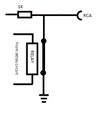
You can try my solution too,
the 1K resistor will make sure You do not burn the output stage, the relay should short the output after the resistor when not energised.
thisway the signal does not has to pass the relay contacts.
as a bonus it keeps the power amplifier input shorted.
to provide a load for the pre-amp so it won't see a dead short, and burn the output stage.
You can try my solution too,
the 1K resistor will make sure You do not burn the output stage, the relay should short the output after the resistor when not energised.
thisway the signal does not has to pass the relay contacts.
as a bonus it keeps the power amplifier input shorted.
Attachments
wrong, the 47K is needed.
to provide a load for the pre-amp so it won't see a dead short, and burn the output stage.
How so ?
If you look at the diagram its permanently connected between the output and ground. It serves no purpose.
You can try my solution too,
the 1K resistor will make sure You do not burn the output stage, the relay should short the output after the resistor when not energised.
thisway the signal does not has to pass the relay contacts.
as a bonus it keeps the power amplifier input shorted.
That is what I have been saying from the start except that going as high as 1k will have the purists complain about the now higher output impedance. See posts #41, and then, having seen and considered the circuit I still feel my original judgement is OK and that the 47 ohms will be fine.
Its Zebra's choice of course which route to follow, series or shunt and if shunt, whether to opt for high or low output impedance.
The relay I have chosen is a small signal relay (CP Clare; CUPP002A124). It *shouldn't* cause any issues being in series with the output.
The relay contacts should closed after 3 to 5 seconds or so after the amplifier is powered up, then open around 200 to 500msec after the power is removed. In effect, the output will see a 47k load with the resistors in place and the relay contacts open. With the 47k resistors removed, it will be the same as powering the amp up with no power amp connected.
The relay contacts should closed after 3 to 5 seconds or so after the amplifier is powered up, then open around 200 to 500msec after the power is removed. In effect, the output will see a 47k load with the resistors in place and the relay contacts open. With the 47k resistors removed, it will be the same as powering the amp up with no power amp connected.
How so ?
If you look at the diagram its permanently connected between the output and ground. It serves no purpose.
That is what I have been saying from the start except that going as high as 1k will have the purists complain about the now higher output impedance. See posts #41, and then, having seen and considered the circuit I still feel my original judgement is OK and that the 47 ohms will be fine.
Its Zebra's choice of course which route to follow, series or shunt and if shunt, whether to opt for high or low output impedance.
the 47 K resistor would prevent a floating output.
that is why its reasonable to have it.
1K seems high, but the preamp manufacturer states a minimum of 600 ohm load to operate the pre-amp safely. given a poweramp has past 20K input impedance, 20 or 21 K ohm to drive makes about no difference, but it is safer to use 1K instead of 47 ohm.
Yes, You did suggest this, and i told, the device is not short circuit proof, and most likely a direct short at the output might damage it. Hence i did link the schematic. The solution You offered is different to mine only in the load impedance seen by the pre-amp while the relay is shorted to ground.
nothing else.
That is what I was reffering to, 47 ohm is far less than 600 ohm claimed by the manufacturer of the pre-amp. Read back, this is why i suggest the 1K ohm resistor. Won't hurt anything, and can save a few transistors.
the 47 K resistor would prevent a floating output.
that is why its reasonable to have it.
Its not really floating in the true sense because its an active output stage. As far as the connected power amp input goes, that sees either an "open" on its input or else a "connected to preamp" condition depending on the relay state. The preamp output doesn't need ground referencing when the relay is open and the power amp off... nothing ever connects to it in that state. When power is initially applied, the relay has already been through its delay time before it connects and in that time the preamp has settled to its nominal zero volts output.
the relays contacting to a floating output can make a pop noise.
have the 47K there, and the output is not floating.
if the input cap charging is the reason for plopping, then if You leave the output floating, the relay will not solve the issue. pop will be there as soon as the relay contacts connect the power amp.
at least as far as i know 😀
makes perfect sense to me, the 47K ohm resistor there is more than valid.
oh, zebra, be aware that a poweramp with floating input can buzz.
i would suggest my solution, as the poweramp would see a shorted input and not buzz with the floating input untill the relay kicks in.
i usually go by this setup.
Last edited:
🙂 We will have to agree to disagree on this. The relay never closes (or opens) on a floating condition of the preamp output. On power off, the relay opens before the rails have collapsed. That's the whole point of it. On power on it delays before connecting. The 47k serves no purpose.
(The input to the power amp is another subject altogether. If AC coupled then there should be a pull down resistor to ground included in the power amp design. That is all circuitry to the right hand side of the relay though, which we have not seen)
(The input to the power amp is another subject altogether. If AC coupled then there should be a pull down resistor to ground included in the power amp design. That is all circuitry to the right hand side of the relay though, which we have not seen)
- Status
- Not open for further replies.
- Home
- Amplifiers
- Chip Amps
- Preamp "pops" on switch off