Hello,
thanks for the triode curves.
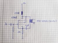
Ub=250V, Ia=10mA, Anode choke is Lundahl LL1667/15mA with a static resistance (series connected) of 2.4K Ohm and 270H.
thanks for the triode curves.
Ub=250V, Ia=10mA, Anode choke is Lundahl LL1667/15mA with a static resistance (series connected) of 2.4K Ohm and 270H.
I wouldn't consider that low for that particular valve. Is this for a linestage?
I would recommend a cathode bypass cap though. Also if you move the 2uF cap up between the plate and OT, the B+ voltage won't appear on the primary winding of the OT.
I would recommend a cathode bypass cap though. Also if you move the 2uF cap up between the plate and OT, the B+ voltage won't appear on the primary winding of the OT.
If you are planning on using a grid cap anyways, why not just use battery bias on the grid and ground both the cathode and the parafeed transformer. Why avoid the cathode circuit, when you can eliminate it?
You could also replace the choke with a CCS. It would be a better load, and it would save your quite a bit of cash.
You could also replace the choke with a CCS. It would be a better load, and it would save your quite a bit of cash.
Hello,
thanks for the triode curves.
Ub=250V, Ia=10mA, Anode choke is Lundahl LL1667/15mA with a static resistance (series connected) of 2.4K Ohm and 270H.
Rk = 2K so at Ik = 10 mA: Vk = 0.01 x 2000 = 20 V (or Vg1 = -20 V)
Rldc = 2K4 so Vl = 24 V
So Vak = 250 – (Vk + Vl) = 250 – (20 + 24) = 206 V
But looking at the curves for the pentode section of the 6BM8, at Vg1 = - 20 V and Vak = 206 V, it would have to pass about 31 mA.
I think that to get 10 mA, Rk should be 2K7 so to get Vg1 = -27 V.
This contribution says nothing about wether you would run the tube too cold, wether it would sound right, wether you would have too much distortion, etc.. This contribution is just about the numbers.
Last edited:
Thank you, Robert.
Your calculation is about the values for 6BM8 operating point. No problem to adjust that for a different value, but my question was about the (relative) low primary impedance of the Sowter line output transformer (model 1010), which has been designed for a low impedance cathode follower output and wether if would be high enough for this anode-cathode loaded output schemo used by Western Electric in their old tube amp days.
Telefunken (TAB) did another variant of this line output in their famous V76 studio tube amps, altough with a much higher ratio (50K: 600 Ohm) on the output transformer. Thats where my questions occur, but their schemo is slightly different to the old WE designs.
Maybe a cathode bypass would lower the output resistance of the circuit?
Attachments

Last edited:
Well, I could be wrong here but it seems to me (1st post) that the anode choke and the IT primary are in parallel wrt the anode. That would implicate their values subtract and would call for a very high self inductance IT to maintain adequate LF response.
To bring more light in it, here are the two input and output loops contained in my schemo.
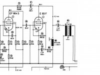
Bay Area Tube Festival
It's a standard coupling circuit which could be found in the WE 92 amp and in some other models of their famous product range.
They used it as a parafeed 4K:2K output in their 32A model.
Unfortunately, I miss data for the WE 285B interstage trans.
Bay Area Tube Festival
It's a standard coupling circuit which could be found in the WE 92 amp and in some other models of their famous product range.
They used it as a parafeed 4K:2K output in their 32A model.
Unfortunately, I miss data for the WE 285B interstage trans.
Attachments

Last edited:
At low frequencies a current source has a high impedance where a choke has low impedance, not? In your suggested circuit (below) the choke takes part of the output circuit. Hence the interstage primary receives less energy at low audio frequency.
If you are uncertain how to calculate the necessary inductance for the IT primary for say -1dB @20Hz, there are enough examples around at the forum which I do not know by heart 😉
If you are uncertain how to calculate the necessary inductance for the IT primary for say -1dB @20Hz, there are enough examples around at the forum which I do not know by heart 😉
Attachments
Last edited:
Yes, true statement. WE had no ideal current source available, so I think thats an idealistic and simplified theoretical approach. In real life, WE arranged the parafeed output without an ideal current source but using chokes and resistors as plate loads.
Western Electric - Rosetta Stone for Triodes
Western Electric - Rosetta Stone for Triodes
impedance is...
2*pi*frequency of interest*inductance = impedance
If we rearrange the equation to find inductance we get the following.
impedance/(2*pi*frequency) = inductance
we now plug in our numbers and solve.
15K/(2*pi*20) = ~120H
This means that if you had a plate choke with infinite impedance you would need a minimum of 120H on the primary of your transformer in order to achieve a frequency response of -3db at 20hz.
This doesn't take DCR, loading, or anything else into consideration.
This is to arrive at a mediocre -3dB @20Hz. Then there is degenerative choke capacitance and IT HF behavior also to overcome.
Plate choke in my schemo was oriented by famous TAB V76, 270H. Just the tube has been changed to a low impedance trioded pentode instead of a E83F pentode. Current is nearly the same, too. The only difference is, output transformer is coupled at the cathode of the tube instead at ground. It's not a question of wether the principle is working or not, it's just a question of "how low can you go" with the output trannies primary impedance.
Yeup.
Honestly I would not use a circuit like this for a preamp. If you want to keep gain to a minimum and have a really low output impedance, just use a cathode follower with a step up input transformer.
The step up transformer gives you your gain, your tube gives you your low output impedance. Not to mention that your audio path loops actually become less complex than the WE circuit.
Member
Joined 2009
Paid Member
Well, that depends on the exact value of the primary inductance. You could buy a cheap digital meter and measure this property. Or you can ask the builder, it is a good habit to publish data and provide it with the product.question is how low can you go with the output trannies primary impedance.
You must understand that inductance is a property of a coil where impedance is derived from the frequency at which the coil is operated. For LF there is a point at which the drop off reaches -3dB. For hifi it is nice to have this point at 10Hz, so at 20Hz the loss will be a hardly noticeable -1dB.
Thanks for calculating, euro21.
Primary DCR of the Sowter is 99 Ohms (measured), inductance L=97H. Means the parafeed output transformer has roughly the same inductance as the output tube (at 10 Hz).
Will that be sufficient for my drawn schemo?
Primary DCR of the Sowter is 99 Ohms (measured), inductance L=97H. Means the parafeed output transformer has roughly the same inductance as the output tube (at 10 Hz).
Will that be sufficient for my drawn schemo?
Attachments

Last edited:
- Home
- Amplifiers
- Tubes / Valves
- Preamp parafeed output WE style