Consider a real center tap secondary, versus a Pseudo center tap using 2 resistors.
Suppose there is a small difference in the preamp's chassis ground voltage, versus the power amp's chassis ground voltage. You might think it is not a problem, if it is caused by a high impedance voltage/current difference.
That could be Power Mains difference, switcher supply, or any other voltage difference. These things cause ground loops between two equipments.
That is a potential (no pun intended) cause of hum, noise, grunge, etc.
If that interference voltage is coupled from the transformer primary to the secondary (example: capacitive coupling), and the secondary has a center tap that is grounded, then that common mode interference is mostly shunted out to ground.
Even if the primary and secondary are shielded from each other, the shield has to be grounded to either the preamp, or to the power amp. But that shield is at ground of one equipment, so the capacitance of the shield to the other winding couples the voltage as interference.
But, If that interference voltage is coupled from the transformer primary to the secondary (capacitive coupling), and the secondary has pseudo center tap resistors, that will develop a common mode interference voltage signal to both grids of the power amplifier.
The voltage will be 'interference signal voltage' x 'pseudo center tap resistance'.
Best case: common mode signals cancel from appearing at the output, if the next stage is perfect.
But that will still rob current all the way at the push pull output stage.
Worst case: common mode signals are not cancelled out. You will hear the interfering signal.
Even if they are cancelled out due to perfect balance, the signal may inter-modulate with the desired music signals.
Last edited:
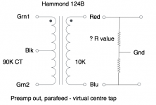
Thanks for the detailed explanation. I'd like to hook this up and try it, so could you help me by telling me what value resistors I should use? And whether I use two resistors with a centre ground as shown, or whether it would work as a balanced out without the resistors, i.e. with the secondary floating and pin 1 of the XLR connected to preamp ground?
With the original post, no specific design goals are being made.
The member wrote about balanced/pp output. Both are different from each other and hence have different topology.
A balanced output can be made from any SE output stage by using a transformer.
A push-pull output is different to that, because it splits phase and therefore needs a phase splitter stage before the output stage.
The phase split can be made with another transformer, or electronic tube/SS.
A balanced output needs no phase splitter stage and is much easier to achieve.
Jensen 10k61-1m transformer works well for 0DC se to balanced duties and does not need a huge cap to work. Just keep the driving impedance under 3K or so. If I was to try a PP output transformer in parafeed to balanced out, my first try would be to float the secondary and take pin 1 to chassis ground on the source side only.
Jensen 10k61-1m transformer works well for 0DC se to balanced duties and does not need a huge cap to work. Just keep the driving impedance under 3K or so. If I was to try a PP output transformer in parafeed to balanced out, my first try would be to float the secondary and take pin 1 to chassis ground on the source side only.
Thanks for that. I'm in the UK so I usually avoid buying from the USA because of shipping and handling charges. But I'll try exactly what you say - float the secondary and connect pin 1 to chassis ground on the source side only. Seems the right way to do it.
124B not for preamplifier output but splitter stage
you need 1140-LU-A
https://www.hammfg.com/files/parts/pdf/1140-LU-A.pdf
you need 1140-LU-A
https://www.hammfg.com/files/parts/pdf/1140-LU-A.pdf
124B not for preamplifier output but splitter stage
you need 1140-LU-A
https://www.hammfg.com/files/parts/pdf/1140-LU-A.pdf
Thanks for that. Looks good, especially being nickel. Not sure if I need 4:1 step-down but worth looking at.
- Home
- Amplifiers
- Tubes / Valves
- Preamp output - SE to balanced choices?