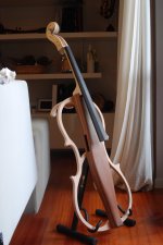
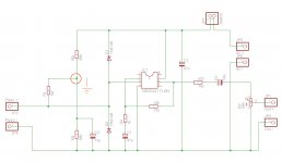
Hi guys, I built a preamplifier for a piezo mic for my DIY electric cello. The circuit is the following
I am not able to remove a strong oscillation which makes it unusable. Do you have any suggestions for me?
This is the piezoelectric:
RS PRO Vibration Sensor -15degC → +55degC, Dimensions 15 x 1.5 x 0.6 mm | RS Components
Thank you all, Jago
I am not able to remove a strong oscillation which makes it unusable. Do you have any suggestions for me?
This is the piezoelectric:
RS PRO Vibration Sensor -15degC → +55degC, Dimensions 15 x 1.5 x 0.6 mm | RS Components
Thank you all, Jago
Attachments
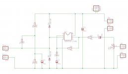
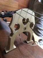
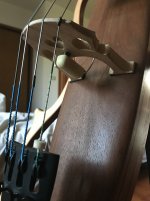
How have you mounted the piezo? The best place is under the bridge. However I think you would probably be better off with one of the rod pickups especialy made for instruments here 1X( Acoustic Guitar Piezo Under-Saddle Pickup S2B8) 4894462342015 | eBay . Your input impedance for your preamp (R1) is a bit low. I probably would use 4.7M to 10M.
The common point between R2 and R3 is the virtual ground of the circuit.
Connect all the ground points there and not to the (-) point of the battery.
Connect all the ground points there and not to the (-) point of the battery.
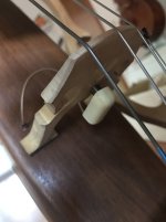
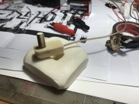
The sensor is already installed on the instrument. The piezo is shielded and drowned in a two-component resin, in a DIY silicone mold. Output is a shielded good quality cable.
What are the signal ground I should connect between R2 and R3? The shield metal box and what else?
Thanks!
What are the signal ground I should connect between R2 and R3? The shield metal box and what else?
Thanks!
Attachments
Sorry my mistake. Forget my comment.
I have not seen that the power supply was only a 9V battery.
I have not seen that the power supply was only a 9V battery.
Add 10pF across R5, if using the 5534 you also need 100nF ceramic cap between pins 4 and 7 (close to the 5534), always needed for proper performance of this chip.
A better circuit might be to use the opamp as a transimpedance stage, not a voltage amp stage, and with a JFET opamp (very low current noise).
That would prevent the 5534 from working, and the JFET option would be required. The 5534 has a worst-case input bias current of 1.5µA, which into 1M is 1.5V offset, just tolerable from 9V supply, any more and it would saturate at the rail.I probably would use 4.7M to 10M.
A better circuit might be to use the opamp as a transimpedance stage, not a voltage amp stage, and with a JFET opamp (very low current noise).
I nearly did something similar for my acoustic guitar, some years back.
I bought a Dean Markely piezo pickup for under the bridge, which is great as it comes with a strap button Jack socket.
I looked at simple charge amplifiers for the piezo pickup, as I was led to believe this is the best way to utilise piezo pickups.
Never got around to trying it, maybe worth a shot?
Charge amplifier for piezoelectric sensors with balanced impedances at... | Download Scientific Diagram
Thanks for your advice. I will try what is suggested. If you have a better circuit ...
Thanks for the PDF of the Electric Violin, it's too complex for my needs but it's very interesting.
I will update you on the new tests.
Thanks for the PDF of the Electric Violin, it's too complex for my needs but it's very interesting.
I will update you on the new tests.
Hi, the schematic I posted was just a link to a site showing an image of the circuit.
I'm fairly sure I found a simple circuit here, on Diyaudio.com...
I think it was this thread:
Piezoelectric Transducer Preamp
The TI sloa033a datasheet in post 6 is particularly useful
I'm fairly sure I found a simple circuit here, on Diyaudio.com...
I think it was this thread:
Piezoelectric Transducer Preamp
The TI sloa033a datasheet in post 6 is particularly useful
Last edited:
NE5534 is not first choice for 9V applications:
-poor output level
-high current consumption
-high input bias current
-high input noise current
For a piezo tranducer the TL061 is a better choice.
-poor output level
-high current consumption
-high input bias current
-high input noise current
For a piezo tranducer the TL061 is a better choice.
I agree.
LF351/3
TL06*, TL07, or other jFET are the best choice.
The datasheet just gives design guidance
LF351/3
TL06*, TL07, or other jFET are the best choice.
The datasheet just gives design guidance
Years ago I was using a piezo sensor as an accelerometer sensing movement of a woofer cone. I used a charge amplifier configuration, the only way to keep noise pick-up low enough while getting the extended low-frequency response I needed.I looked at simple charge amplifiers for the piezo pickup, as I was led to believe this is the best way to utilize piezo pickups.
Never got around to trying it, maybe worth a shot?
Charge amplifier for piezoelectric sensors with balanced impedances at... | Download Scientific Diagram
I've never used a charge-mode amp for a musical instrument piezo, simply because my guitars all came with factory piezos and onboard preamps. But I agree that charge-mode is a very good idea - it has a very low input impedance, and that solves a lot of noise and interference problems.
The circuit shown in this thread has inadequate input impedance (you want 10M for R1, not 1M), and the 5534 is absolutely not an option - use an FET-input op-amp such as the TL061 or TL071, or a more modern flavour of JFET-input op-amp.
A charge-mode circuit, by contrast, has an extremely low input impedance, but you still need an FET-input op-amp, so that the tiny signal current from the piezo goes where it's supposed to go (into the feedback network), and not into the (-) input pin of the op-amp!
-Gnobuddy
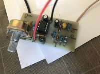
I made these circuit changes as you suggested:
I added 100nF to pin 4-7 power supply IC
I used TL061
I added 18 pF (I don't have 10 pF) across R5 (10K)
It seems to go much better, now I try with a good shield
Tomorrow I will do the tests on the instrument ...
Thank you very much
I added 100nF to pin 4-7 power supply IC
I used TL061
I added 18 pF (I don't have 10 pF) across R5 (10K)
It seems to go much better, now I try with a good shield
Tomorrow I will do the tests on the instrument ...
Thank you very much
- Status
- Not open for further replies.
- Home
- Live Sound
- Instruments and Amps
- Preamp for piezo sensor