Hi
First i think it's proper for a short introduction of me and the reason for this project. I'm studying for a masters in electrical engineering, most of the courses has been towards the analog domain, none towards digital hardware. Before now that is, this is for a project course and the goal of the course is to make a system with both digital and analog electronics and some programming.
My suggestion was to build a preamp with a DAC included, the plan is to have both a analog input (no AD conversion), a spdif input and a single stereo output, maybe a headphone output if time allows. The plan is to keep things simple without compromising to much in quality.
The project will get some funding from the school and the rest from my pocket. So the component cost should not be to high, around 150$ give or take. My current system is not worth mentioning but it will be upgraded if/when i get some cash, thats where and when the preamp comes in...
The final PCB will be ordered from china so multilayer is possible. When it comes to soldering the equipment at school is good, SMD is preferred. But i would like to avoid things like ballpoint packages if possible, as long as the components have legs i should manage 😉
Requirements:
uC for controlling various buttons and functions, it should also be able to do some signal processing. An idea for a future project to measure a speaker and make software compensation and filtering. The plan was to use the uC for decoding the spdif signal as well.
I don't have any real experience with uCs so one with pre-made drivers and large forum support is preferable (planning on C programming). I'm taking a course with AVR butterfly atm. but i have been looking towards blackfin as well for the uClinux support. The volume and other settings should be kept if the power is lost so a non-volatile memory is required.
Remote control for volume control, source selection and similar.
Analog and spdif input, single analog output. Volume control for both the digital and analog signal.
The supply will probably be a toroid transformer and then separate regulators for the different parts.
What i need help with now is mostly the component selection. There is a huge amount of information on this forum alone, i have gone trough some but far from all.
uC:
Here i need lots of help since i don't know where to start 🙁
DAC:
CS4398 and AD1853 seems to be popular and fairly easy to implement which is preferable. Are there any more similar chips that should be considered?
Opamp:
Maybe OPA132UA? I have read a few of the post in the opamp thread by Andrea: and this came up early and its both cheap and available 😀
https://production.diyaudio.com/community/index.php?threads/154106/
Volume control:
The teacher suggested PGA2310, this will make it easy to control the volume with remote control but some solution for the analog turn wheel is needed instead.
Modular design:
Yes please. If it is possible without to much extra work the plan is to make the design modular to simplify for future projects. Or if someone else would like to play with the design.
I hope someone has the time to read all of this and leave some constructive comments.
Best regards // Rikard
For a good PIC based remote volume (motorised pot) and comprehensise programming options this is excellent,
FPRC5RX - DIY learning IR decoder
You can't beat a good ALPS pot for quality IMO as against an electronic option.
Source switching... my prefered option is discrete FET's as close to the inputs as possible... possibly with a buffer stage before.
FPRC5RX - DIY learning IR decoder
You can't beat a good ALPS pot for quality IMO as against an electronic option.
Source switching... my prefered option is discrete FET's as close to the inputs as possible... possibly with a buffer stage before.
The plan was to use the uC for decoding the spdif signal as well.
🙂🙂🙂
It's quite an ambitious project... as a lot of things come into play. I am thinking physical layout, grounding etc... all have to be done right for it to be a top performer.
My programming skills aren't up too much I'm afraid 🙁 Wouldn't know where to begin trying to decode SPDIF from scratch.
A modular approach is good though ... have done that before now.
My programming skills aren't up too much I'm afraid 🙁 Wouldn't know where to begin trying to decode SPDIF from scratch.
A modular approach is good though ... have done that before now.
Instead, the OPA132 is OPA2132 should keep doing? Personally, with 2132, which, OPA134 or OPA2134 I literally could not look, feel a big difference.
Or like MUSILAND SVDAC05 AND MD10
OP275 and matching the CS4398 seems to be doing fine with it.
I think this sounds fine, but the CS4398, RMAA when DYMAMIC RANGE, SNR measurements have not personally come to ingratiate WOLFSON, or TI D / A CONVERTER that will be used.
But CIRRUS LOGIC D / A converters are positive, negative differential consideration to the operation of the circuit impedance matched to the reference circuit has a data sheet. As part as the value of the specification to obtain and to have made a good enough measure of CS4398 are confident the results will come.
hi QRikard ,
this sounds quite interesting. from my experience i can tell:
the pga2310 is quite good for preamps, the cs4398 can sound excellent (my gigaworks has it)
concerning the pga u might have a look at this page: krishu.de » LSQR2: Digital gesteuerter analoger Vorverstärker 2.0
it is german but maybe you can make some use out of the boardlayouts/pictures
i dont know if this is a help since i cant "develope" such things myself, i only build what i can get and then see if its good or not 😛
I built a dual mono block amp and pre-amp while in school... still have them 25+ years later..... 🙂
jk
jk
Mooly:
Thanks for the link, will go trough that mote in detail later. I have a hard time to decide about the pot, personally i was planing to go for a normal rotary potentiometer. But then the remote control came along which makes things more complicated, so im intrested in all options available.
I have done a few PCBs before, sure none of this magnitude and complexity. But I'm actually looking forward to this part, i think its fun to lay the puzzle even if it will take a lot of time since im a perfectionist when it comes to these things. If required i can get help from my teachers because they have more practical and theoretical experience in this area.
We will see about the spdif, i have been looking at the CS8416 which could work as a backup solution. But from my understanding the spdif signal is fairly simple to decode, one main problem seems to be timing.
xTr3Me:
CS4398 has the upper hand at the moment, i will have to look into this further to get impedance matching and a good opamp.
My german is terrible or worse 😛 but google translate made things a lot easier. The schematics are good, will probably take a closer look tonight.
My main fear of this project is the programming and uC interface, this is also one of the main reasons for this project.
skumi:
I have taken a look at OPA132 and OPA134, to me they look really similar so which one is recommended? The OPA134 is slightly cheaper but not much, and i might use the dual package depending on layout but that will be decided later.
The SVDAC05 and MD10 looks really nice, the more projects i find the more popular the CS4398 seems to be. Is there any advantage of using OP275 compared to OPA132/4?
jstang:
I have also recently made a dual mono block class AB amp (2*40W). Its not 100% complete yet, some soldering, measurements and report writing left. It sounds pretty good, but there is a soft whistle in the higher frequency range (only heard when i placed my ear near the speaker element).
This was during a test in the lab right beside all the other electronic equipment so that might have something to do with it.
If any one have any tips for the uC and other peripherals that would be highly appreciated.
A good solution for a volume control would also be great, motorized pot sounds best so far. What im afraid of with this solution is the final sound quality, but i need a solution that can be controlled with a turn knob and remote control.
Thanks for all the tips so far // Rikard
CS4398 has the upper hand at the moment, i will have to look into this further to get impedance matching and a good opamp.
Maybe you should try some line trannies first. they sound better than opamps to me and also to a lot of other people in this thread: gigaworks dac
that might be interesting, i dont want to tell you what to do but that might be an idea 😉
greetings,
chris
Maybe you should try some line trannies first. they sound better than opamps to me and also to a lot of other people in this thread: gigaworks dac
that might be interesting, i dont want to tell you what to do but that might be an idea 😉
greetings,
chris
Im always open for suggestions, since im new to this area i have a lot to learn so all tips are appreciated. A link to a good site makes it so much easier to find the relevant information.
I have started reading that thread but it will take some time, only 1600 posts left...
But so far the transformer mod definitely sounds interesting, the main problem is the cost. The opamp solution is cheap, simple and straight forward so that might be the way to go this time, but i will make the output of the chip ready for a future upgrade to transformers or other.
The design will be modular, the question is how and what parts that can be separated? The DAC chip feels obvious and so does the output from it so the current plan is to make the DAC in a separate PCB and use that as a bridge between the other digital parts and the analog stage.
One more question, how should the connection be made between different blocks?
A simple solution is to use a normal pin header. But will this open up for more distortion in some way and are there any side effects for this solution?
I think its high time for a small update...
Some components have been chosen:
DAC -> CS4398
Receiver -> CS8416
uC -> AT91SAM7Sxxx
UART/DBGU -> MAX3232
These are the main building blocks, and the schematic is one the way. The current schematic is made to get all signal paths right so no EMC is taken into consideration at this point to reduce complexity and component count. Currently the JTAG (10 pin), DBGU/UART, USB and a simple AD input is implemented in the schematic.
The plan is to place the DAC on a separate board and make the board act as a bridge between the main board and the preamp stage. This way it will be easy to change DACs and output stages. I plan to use a simple pin header, hopefully this will not cause any problem with interference.
To make it easier to move things around the enclosure I'm thinking of making a small board with the input contacts. So it can be mounted directly on the chassis wall and then use a logical buffer and send the signals to the CS8416 trough wire.
Will this solution give much problem when it comes to noise or can it be managed?
pin headers are actually the ideal way to connect things if they cannot be on the same PCB, IMO there is no better way as long as a good low impedance type is used. ARDUINO would have been my choice for the uC, but perhaps cost would have been a problem, though this could also be used to control a relay based volume control for the preamp as well as monitoring certain other parts of the circuit like heat, levels etc good for brownie points 😀 your solution for the MUX seems workable, noise should not be unmanageable provided good layout and wire routing is observed.
other than that i'm quite impressed with your ambition, good luck!!
other than that i'm quite impressed with your ambition, good luck!!
Time for another update.
Line transformers will be used on the DAC output 😀 thanks to edcorusa for sending me a pair of samples (XSM600/600 1:1 transformers). These can be used to get complete separation between the DAC and preamp. The downside of this solution is that if I'm going to use the CS3310 volume control it could be a problem with the connection between the preamp and uC.
I have also received samples from cirrus logic with CS4398, CS8416 and CS3310 which reduced the final cost from my part significantly. I don't feel like changing the uC now, because it would take so much time to start all over with the schematic...
MUX vs Analog switch?
Here is a fun part i started thinking about, is there any advantage between using a digital MUX compared to using a analog switch (low impedance bypass)?
The reason is that the signal coming from the uC and receiver should be good and in no need for buffering. So why add a buffer with its own slewrate and other limits when a clean bypass can be used?
Another major advantage of a analog switch is that it can be used as a de-MUX as well when required. There is only one major problem, i haven't found any decent analog switches. I was thinking of "making" one by my self using a bunch of transistors with low on-resistance. Speed is not an issue in my case, the goal is simply to change between two signals and if that takes 50ms or 10ns doesn't matter.
Hardware vs software:
I have been a little lazy to be honest, because the goal was to make it possible to drive most thinks using both hardware and software. But this turned out to increase the component count and complexity a lot. So most parts will be controlled by software only, I will probably have pay for this later...
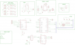
Schematic:
This is a preliminary version, so if anyone has time please take a look at the signal paths to see if I have made any mistakes. All unconnected wires going up should be connected to a supply, and the ones going down to ground. No consideration is taken to EMC or stability, this will start when i know more about the supply.
Line transformers will be used on the DAC output 😀 thanks to edcorusa for sending me a pair of samples (XSM600/600 1:1 transformers). These can be used to get complete separation between the DAC and preamp. The downside of this solution is that if I'm going to use the CS3310 volume control it could be a problem with the connection between the preamp and uC.
I have also received samples from cirrus logic with CS4398, CS8416 and CS3310 which reduced the final cost from my part significantly. I don't feel like changing the uC now, because it would take so much time to start all over with the schematic...
MUX vs Analog switch?
Here is a fun part i started thinking about, is there any advantage between using a digital MUX compared to using a analog switch (low impedance bypass)?
The reason is that the signal coming from the uC and receiver should be good and in no need for buffering. So why add a buffer with its own slewrate and other limits when a clean bypass can be used?
Another major advantage of a analog switch is that it can be used as a de-MUX as well when required. There is only one major problem, i haven't found any decent analog switches. I was thinking of "making" one by my self using a bunch of transistors with low on-resistance. Speed is not an issue in my case, the goal is simply to change between two signals and if that takes 50ms or 10ns doesn't matter.
Hardware vs software:
I have been a little lazy to be honest, because the goal was to make it possible to drive most thinks using both hardware and software. But this turned out to increase the component count and complexity a lot. So most parts will be controlled by software only, I will probably have pay for this later...
Schematic:
This is a preliminary version, so if anyone has time please take a look at the signal paths to see if I have made any mistakes. All unconnected wires going up should be connected to a supply, and the ones going down to ground. No consideration is taken to EMC or stability, this will start when i know more about the supply.
Attachments
I'm not sure line transformers are useful here between the DAC and preamp - there is no (long) line between the DAC and the preamp.
MUX vs Analog switch: You woud need to get the timing so that just one analog switch is on at the time - I would not spend time and risk problems on an analog switch solution.
ADC-Input: I guess you could omit an op-amp-buffer. As I can see it just buffers some centimeters pcb-wire.
What uC is U1 on the schematic?
A wish regarding (inter-PCB) connetctions: Please allow enough space to place a proper connector (e.g. [FONT=arial, helvetica, verdana, geneva]JAPAN SOLDERLESS TERMINALS - B2B-PH-K-S(LF)(SN) - HEADER, TOP ENTRY, 2WAY, Farnell No. [/FONT]9491856) or space for a screw terminal. My experience is pin headers with a low count of pins (<~8) and without lock don't provied reliable connections.
- Status
- Not open for further replies.
- Home
- Source & Line
- Digital Line Level
- Preamp & DAC project