I just bought a tube preamp. It uses two 12AT7, one per channel, and I know it also uses feedback around the circuit. Gain is 20dB and output impedance is low, 200 ohms. What circuit(s) could this be? SRPP, for example? I'm just curious to understand this better as a newbie
What circuit(s) could this be?
Two consecutive common cathode voltage amplifying stages with NFB from the plate on 2nd triode to the cathode of the 1st triode.
It could also be a common cathode into a follower with feedback given to first tube grid, no?
And until the OP brings more info to the table, speculation is the only thing going.
It could also be a common cathode into a follower with feedback given to first tube grid, no?
Could be - either one gain stage with less feedback or two with more could result in 200 ohm z out. Input impedance would tell you which you have. One stage with plate (or follower output) to grid forces a lower input impedance.
It could be a bootstrapped-pair with parallel NFB from the output of the cathode follower to the grid of the input tube.
Just having some fun with it...
Just having some fun with it...
Why don't we all just wait until the original poster provides a schematic? 😀
An excellent idea! 😉
A dual triode 12AT7 that has several milliamps through it has a transconductance, gm, of about 5,000uMhos.
Use one of the triodes as a cathode follower, with several milliamps through it, and the output impedance will be approximately 200 Ohms.
(A cathode follower does have intrinsic local negative feedback).
Intrinsic local negative feedback is the very nature of a cathode follower.
Put a 12At7 triode gain stage in front of the 12AT7 triode cathode follower, and then you can adjust the first stage gain, and cathode follower loss, to have a total gain of about 20dB, and an output impedance of 200 Ohms (it is not necessary to use global negative feedback in that kind of a preamp). That is how I would do it.
Or, to use global negative feedback, as was mentioned earlier in this thread . . .
By bringing the negative feedback signal to the input stage grid. But that will cause the input impedance to be quite low.
What is the rated input impedance? . . . (not the input resistance, the input impedance).
Quite often, marketing cheats, and lists the input resistance, and calls it input impedance (may be true at DC).
But often at 1kHz, and at 20kHz, the impedance may be much lower than the marketing/sales brochure says it is.
marketing games are like political games (just my opinion)
No schematic?
Open it up, draw a schematic, post the schematic here, and learn something.
Are you worried about voiding the warranty (if the unit ever breaks within the warranty time, would it be worth the time and money to ship back to China, have them fix it, and charge you to ship it back to you).
Oh, perhaps it is a local product that has a good warranty policy, and can be fixed locally under warranty.
Last edited:
Taking bets! Taking bets!!! Multiple configurations allowed!! Just don´t introduce dirty silicon devices into them!!! $5 minimum per bet!!!

😀😀😀
The original poster didn't come here looking for a design; he just wants to know what he has. Until (unless?) he can provide a schematic or some other documentation there really isn't much to say.
The original poster didn't come here looking for a design; he just wants to know what he has. Until (unless?) he can provide a schematic or some other documentation there really isn't much to say.
There have been 7 requests for more information from the original poster.
Where is he?
Please, we need some documentation about the pre-amplifier. This is the eighth request for more information. (8/14)
Taking Bets, well not exactly, just deciding what company to invest in (the stock market).
Where is he?
Please, we need some documentation about the pre-amplifier. This is the eighth request for more information. (8/14)
Taking Bets, well not exactly, just deciding what company to invest in (the stock market).
Last edited:
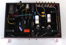
The original poster (me) had the usual long day of work. Here's what I have:
Line Stage Preamplifier – Quicksilver Audio
No
Line Stage Preamplifier – Quicksilver Audio
No
Attachments
Short answer: any one of those suggested above, or even more possibilities still unnamed.What circuit(s) could this be?
That.Until (unless?) he can provide a schematic or some other documentation there really isn't much to say.
In any case, I liked it: looks well made, neat wiring, simple and open layout.
Maybe Factory will supply schematic?
In any case,the simple and open layout allows for your drawing it, by hand.
All it takes is 1 or 2 hours of relaxed evening or night , no active Family or pets nearby , a desk lamp, couple reading glasses, pencil and paper.
Unit unplugged and turned OFF for, say, 1 hour, and a multimeter to read continuity to better trace connections and hidden tracks.
Does not even require disassembly.
Please post what you find, we might help complete any drawing gaps.
In the late 1980s, I bought a Quicksilver KT88 amplifier. Simply as a matter of maintenance and the possibility of needing to repair the unit someday, I wanted to have a schematic on file. I called Mike Sanders and asked him for a schematic. He told me he had never drawn one out and that I should draw it out myself. So that's exactly what I did.
What? The designer/manufacturer of an electronic product never drew a schematic of it? That's not even remotely believable. He could have just said that he was not going to give it to you. At least that would have been an honest answer.
- Home
- Amplifiers
- Tubes / Valves
- Preamp Circuit Question