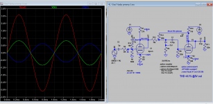
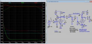
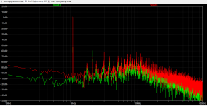
These mods make it easier to change level output by just varying NFB as it's taken from 6p6p cathode and feedback to V1 grid, lower resistor value can be used. Local feedback of V1 is removed. FFT is improved but odd harmonics is still high (mainly generated by output stage), but much lower than the original. Freq response is flat up to 200k.
Attachments
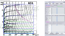
This is 6j4-CH used in the sim:
Code:
**** 6J4-CH ******************************************
* Created on 06/05/2022 19:46 using paint_kip.jar
* www.dmitrynizh.com/tubeparams_image.htm
* Plate Curves image file: 6j4-ch.png
* Data source link: <plate curves URL>
*----------------------------------------------------------------------------------
.SUBCKT 6J4-CH P G2 G K ; LTSpice tetrode.asy pinout
* .SUBCKT 6J4-CH P G K G2 ; Koren Pentode Pspice pinout
+ PARAMS: MU=36.65 KG1=2919 KP=167.65 KVB=246.24 VCT=0.58 EX=1.864 KG2=7119.72 KNEE=8.75 KVC=3.179
+ KLAM=1.884E-12 KLAMG=1.047E-4  KD=1.308 KC=2647.3 KR1=8.496E-10 KR2=0.8101 KVBG=0.0902 KB1=2.386 KB2=0.8178 KB3=0.8949 KB4=1 KVBGI=1.666 KNK=0.375 KNG=0.1505 KNPL=0.4836 KNSL=0.3345 KNPR=1.262 KNSR=11.22
+ CCG=11P CGP=0.15P CCP=6P VGOFF=-0.6 IGA=0.000989 IGB=0.423 IGC=32.64 IGEX=1.817
* Vp_MAX=500 Ip_MAX=20 Vg_step=1 Vg_start=0 Vg_count=16
* X_MIN=70 Y_MIN=59 X_SIZE=592 Y_SIZE=591 FSZ_X=1296 FSZ_Y=736 XYGrid=false
* Rp=1400 Vg_ac=20 P_max=3.5 Vg_qui=-7.5 Vp_qui=300
* showLoadLine=n showIp=y isDHP=n isPP=n isAsymPP=n isUL=n showDissipLimit=y
* showIg1=y isInputSnapped=y addLocalNFB=n
* XYProjections=n harmonicPlot=y dissipPlot=n
* UL=0.43 EG2=150 gridLevel2=y addKink=y isTanhKnee=n advSigmoid=y
*----------------------------------------------------------------------------------
RE1  7 0  1G    ; DUMMY SO NODE 7 HAS 2 CONNECTIONS
E1   7 0  VALUE=  ; E1 BREAKS UP LONG EQUATION FOR G1.
+{V(G2,K)/KP*LOG(1+EXP((1/MU+(VCT+V(G,K))/SQRT(KVB+V(G2,K)*V(G2,K)))*KP))}
RE2  6 0  1G    ; DUMMY SO NODE 6 HAS 2 CONNECTIONS
E2  6 0  VALUE={(PWR(V(7),EX)+PWRS(V(7),EX))} ; Kg1 times KIT current
E4   8 0  VALUE={V(P,K)/KNEE/(KVBGI+V(6)*KVBG)}
E5  81 0  VALUE={PWR(V(8),KB1)}
E6  82 0  VALUE={PWR(V(8),KB2)}
E7  83 0  VALUE={PWR(V(8),KB3)}
E8   9 0  VALUE={PWR(1-EXP(-V(81)*(KC+KR1*V(82))/(KD+KR2*V(83))),KB4)*1.5708}
RE4  8 0  1
RE5 81 0  1
RE6 82 0  1
RE7 83 0  1
RE8  9 0  1
RE21 21 0 1
E21  21 0 VALUE={V(6)/KG1*V(9)} ; Ip with knee but no slope and no kink
RE22 22 0 1 ; E22: kink curr deviation for plate
E22  22 0 VALUE={V(21)*LIMIT(KNK-V(G,K)*KNG,0,0.3)*(-ATAN((V(P,K)-KNPL)/KNSL)+ATAN((V(P,K)-KNPR)/KNSR))}
G1   P K  VALUE={V(21)*(1+KLAMG*V(P,K))+KLAM*V(P,K) + V(22)}
G2   G2 K  VALUE={V(6)/KG2*(KVC-V(9))/(1+KLAMG*V(P,K)) - V(22)}
RCP  P K  1G     ; FOR CONVERGENCE
C1   K G  {CCG}  ; CATHODE-GRID 1
C2   G P  {CGP}  ; GRID 1-PLATE
C3   K P  {CCP}  ; CATHODE-PLATE
RE23 G 0 1G
GG G K VALUE={(IGA+IGB/(IGC+V(P,K)))*(MU/KG1)*
+(PWR(V(G,K)-VGOFF,IGEX)+PWRS(V(G,K)-VGOFF,IGEX))}
.ENDS
*$
Attachments
There are some weird mistakes in that Nobsound preamp schematic.
Where's 0V signal ground?
The 1.5k resistor before the grid of the 6J4 forms a voltage divider with the grid leak (560k). Why would you want to attenuate signal before the feedback loop? That's counterproductive.
Why is there a 2.2uF cap after the plate of the 6V6, then the feedback take-off, and then another 2.2uF cap? I don't think that's necessary. I guess the final output sees a 1.1uF-120k ohm HPF, but the feedback loop sees the signal coming off 2.2uF, so more LF gets fed back than goes out the output(?).
I simulated the circuit as in the schematic, but with the inputs referenced to 0V and the 1.5k resistor moved to work as a grid stopper instead of a voltage divider. It actually looks pretty good.
Open loop gain is 32X. Closed loop gain is just less than 8X. That's 27.5dB of NFB.
Closed loop Zout is 1k ohms. That's not very low, but low enough for use as a preamp.
At 1Vrms into a 10k ohm load, the THD is 0.021%. all H2. THD is half that into a 100k load.
Frequency response is very wide. Lots of bandwidth,
Putting a 1nF cap in parallel with the output makes it ring a little, but not badly.
I tried adding bypass caps to the 330R and 500R cathode resistors, to goose up the open loop gain and reduce the output impedance. I then applied more feedback signal to reduce gain back to 8X. The result was lower output impedance but THD was slightly higher.
For comparison, I can get similarly good looking results from a Salas-style 6V6-triode, all by itself and with no NFB, if I'm willing to use a 400V B+ with a 15k Ra and Ia of 20mA for the 6V6. That gets about the same gain and the same THD, but it does require a higher voltage B+. Similar current load, though.
I guess this Nobsound thing is OK. I've certainly seen much worse!
___________________________
Edit to add: I tried Koonw's 6J4-CH in the first stage and that worked with very slight differences. It does look like 6J4 is the Chinese equivalent of 6AU6A.
Last edited:
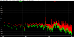
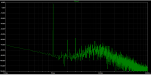
The previous sim is using Ayumi 6v6, distortion increased when time changed from 2m to 50mm for FFT, that is weird.
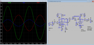
Here is sim based on my own Paint Tool model, all quite normal. (6v6 now generated very little harmoincs on its own):
Here is sim based on my own Paint Tool model, all quite normal. (6v6 now generated very little harmoincs on its own):
Code:
**** 6V6GT ******************************************
* Created on 08/20/2021 15:48 using paint_kip.jar
* www.dmitrynizh.com/tubeparams_image.htm
* Plate Curves image file: 6v6gt.png
* Data source link: <plate curves URL>
*----------------------------------------------------------------------------------
.SUBCKT 6V6GT P G2 G K ; LTSpice tetrode.asy pinout
* .SUBCKT 6V6GT P G K G2 ; Koren Pentode Pspice pinout
+ PARAMS: MU=10.7 KG1=1676.38 KP=46.44 KVB=1412.81 VCT=-0.0399 EX=1.306 KG2=2635.52 KNEE=9.75 KVC=1.67
+ KLAM=1.5E-9 KLAMG=1.35E-4  KD=0.02767 KC=0.2692 KR1=1.112E-5 KR2=0.06456 KVBG=0.01817 KB1=1.299 KB2=3.194 KB3=1.125E-5 KB4=0.98 KVBGI=3.975E-6 KNK=0.1559 KNG=0.00951 KNPL=1.145E-6 KNSL=3.87E-4 KNPR=0.4664 KNSR=84.99
+ CCG=0.7P CGP=9P CCP=7.5P VGOFF=-3.6 IGA=8.688E-5 IGB=0.007008 IGC=15 IGEX=3.236
* Vp_MAX=500 Ip_MAX=140 Vg_step=5 Vg_start=0 Vg_count=14
* X_MIN=37 Y_MIN=25 X_SIZE=731 Y_SIZE=516 FSZ_X=1288 FSZ_Y=723 XYGrid=false
* Rp=1400 Vg_ac=20 P_max=12 Vg_qui=-32.5 Vp_qui=300
* showLoadLine=n showIp=y isDHP=n isPP=n isAsymPP=n isUL=n showDissipLimit=y
* showIg1=y isInputSnapped=y addLocalNFB=n
* XYProjections=n harmonicPlot=y dissipPlot=n
* UL=0.43 EG2=250 gridLevel2=y addKink=y isTanhKnee=n advSigmoid=y
*----------------------------------------------------------------------------------
RE1  7 0  1G    ; DUMMY SO NODE 7 HAS 2 CONNECTIONS
E1   7 0  VALUE=  ; E1 BREAKS UP LONG EQUATION FOR G1.
+{V(G2,K)/KP*LOG(1+EXP((1/MU+(VCT+V(G,K))/SQRT(KVB+V(G2,K)*V(G2,K)))*KP))}
RE2  6 0  1G    ; DUMMY SO NODE 6 HAS 2 CONNECTIONS
E2  6 0  VALUE={(PWR(V(7),EX)+PWRS(V(7),EX))} ; Kg1 times KIT current
E4   8 0  VALUE={V(P,K)/KNEE/(KVBGI+V(6)*KVBG)}
E5  81 0  VALUE={PWR(V(8),KB1)}
E6  82 0  VALUE={PWR(V(8),KB2)}
E7  83 0  VALUE={PWR(V(8),KB3)}
E8   9 0  VALUE={PWR(1-EXP(-V(81)*(KC+KR1*V(82))/(KD+KR2*V(83))),KB4)*1.5708}
RE4  8 0  1
RE5 81 0  1
RE6 82 0  1
RE7 83 0  1
RE8  9 0  1
RE21 21 0 1
E21  21 0 VALUE={V(6)/KG1*V(9)} ; Ip with knee but no slope and no kink
RE22 22 0 1 ; E22: kink curr deviation for plate
E22  22 0 VALUE={V(21)*LIMIT(KNK-V(G,K)*KNG,0,0.3)*(-ATAN((V(P,K)-KNPL)/KNSL)+ATAN((V(P,K)-KNPR)/KNSR))}
G1   P K  VALUE={V(21)*(1+KLAMG*V(P,K))+KLAM*V(P,K) + V(22)}
G2   G2 K  VALUE={V(6)/KG2*(KVC-V(9))/(1+KLAMG*V(P,K)) - V(22)}
RCP  P K  1G     ; FOR CONVERGENCE
C1   K G  {CCG}  ; CATHODE-GRID 1
C2   G P  {CGP}  ; GRID 1-PLATE
C3   K P  {CCP}  ; CATHODE-PLATE
RE23 G 0 1G
GG G K VALUE={(IGA+IGB/(IGC+V(P,K)))*(MU/KG1)*
+(PWR(V(G,K)-VGOFF,IGEX)+PWRS(V(G,K)-VGOFF,IGEX))}
.ENDS
*$
Attachments
I ran the simulation with Koonw's 6J4-CH and 6V6GT models, and got similar results as with the previous models (Ayumi 6AU6A and Adrian Immler 6V6GT). The THD with Koonw's models was twice as high, but still low at 0.025% at 1V rms output into 100k load. I think we have good agreement here.
Koonw, what SPICE directive do you use to simulate harmonic distortion?
Koonw, what SPICE directive do you use to simulate harmonic distortion?
Last edited:
I use only .trans 2m for quick sim, when come to FFT I use .trans 50m. When I switch to .trans 50m (that is the only directive changed) I found THD distortion is >1% @3V out, I found that increased distortion is caused by Ayumi 6v6.inc model found in my PC. Change 6j4-ch.inc to 6aua.inc makes little difference, but change to my 6v6gt model, THD distortion stay the same as I switch trans. time.
So see what result you get:
*
So see what result you get:
*
Code:
* Generic pentode model: 6V6
* Copyright 2003--2008 by Ayumi Nakabayashi, All rights reserved.
* Version 3.10, Generated on Sat Mar  8 22:41:04 2008
*           Plate
*           | Screen Grid
*           | | Control Grid
*           | | | Cathode
*           | | | |
.SUBCKT 6V6 A G2 G1 K
BGG   GG   0 V=V(G1,K)+0.99999998
BM1   M1   0 V=(0.048335289*(URAMP(V(G2,K))+1e-10))**-0.77023894
BM2   M2   0 V=(0.6607234*(URAMP(V(GG)+URAMP(V(G2,K))/7.0192317)))**2.2702389
BP    P    0 V=0.0010053341*(URAMP(V(GG)+URAMP(V(G2,K))/10.623555))**1.5
BIK   IK   0 V=U(V(GG))*V(P)+(1-U(V(GG)))*0.00060166202*V(M1)*V(M2)
BIG   IG   0 V=0.00051429562*URAMP(V(G1,K))**1.5*(URAMP(V(G1,K))/(URAMP(V(A,K))+URAMP(V(G1,K)))*1.2+0.4)
BIK2  IK2  0 V=V(IK,IG)*(1-0.4*(EXP(-URAMP(V(A,K))/URAMP(V(G2,K))*15)-EXP(-15)))
BIG2T IG2T 0 V=V(IK2)*(0.916000233*(1-URAMP(V(A,K))/(URAMP(V(A,K))+10))**1.5+0.083999767)
BIK3  IK3  0 V=V(IK2)*(URAMP(V(A,K))+3125)/(URAMP(V(G2,K))+3125)
BIK4  IK4  0 V=V(IK3)-URAMP(V(IK3)-(0.00061491868*(URAMP(V(A,K))+URAMP(URAMP(V(G2,K))-URAMP(V(A,K))))**1.5))
BIP   IP   0 V=URAMP(V(IK4,IG2T)-URAMP(V(IK4,IG2T)-(0.00061491868*URAMP(V(A,K))**1.5)))
BIAK  A    K I=V(IP)+1e-10*V(A,K)
BIG2  G2   K I=URAMP(V(IK4,IP))
BIGK  G1   K I=V(IG)
* CAPS
CGA   G1  A  0.7p
CGK   G1  K  5p
C12   G1  G2 3.3p
CAK   A   K  6.9p
.ENDShello guys, really appreciate your analysis of the circuit, i cant follow it all, i am not that familiar with circuit theory/design, but from what i gather, with a few tweeks and upgrades here and there the results might be pretty good, although the gain might be too high for my use.
The output from my phono mc stage is the usual 0.4v, Aleph J sensitivity is 1.5v for full output 25w, so i guess a gain of 4 or 5 should be sufficient, say 15dB
Can i ask to summarise and to post an updated schematic with values so i can see how it looks.
Cheers
The output from my phono mc stage is the usual 0.4v, Aleph J sensitivity is 1.5v for full output 25w, so i guess a gain of 4 or 5 should be sufficient, say 15dB
Can i ask to summarise and to post an updated schematic with values so i can see how it looks.
Cheers
I think the original circuit has very high input impedance > 2Meg, making it unsuitable to hook an MM to the input directly, unless you add a 47k resistor in the input as MM load. The line stage has a gain of 8, it's too high for CD as we already know it. The simplest is to add a volume control 47k or so in the input or output. If not satisfied you might want to mod further using my schematic.
Attachments
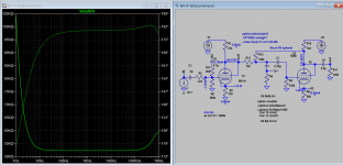
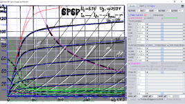
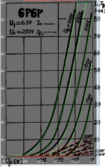
Here is the real 6p6p used in the sim:
Code:
**** 6P6P ********************************posted**********
* Created on 06/06/2022 19:14 using paint_kip.jar
* www.dmitrynizh.com/tubeparams_image.htm
* Plate Curves image file: 6p6p.png
* Data source link: <plate curves URL>
*----------------------------------------------------------------------------------
.SUBCKT 6P6P P G2 G K ; LTSpice tetrode.asy pinout
* .SUBCKT 6P6P P G K G2 ; Koren Pentode Pspice pinout
+ PARAMS: MU=9.74 KG1=3411.36 KP=53.27 KVB=769.03 VCT=0.97 EX=1.423 KG2=6888.2 KNEE=9.75 KVC=1.856
+ KLAM=1.5E-9 KLAMG=5.443E-4  KD=0.06105 KC=0.2488 KR1=1.268E-5 KR2=0.05423 KVBG=0.024 KB1=1.537 KB2=3.13 KB3=1.125E-5 KB4=1.013 KVBGI=2.87E-6 KNK=0.03505 KNG=0.01421 KNPL=1.235E-11 KNSL=0.001114 KNPR=19.5 KNSR=46.92
+ CCG=0.7P CGP=9P CCP=7.5P VGOFF=-3.6 IGA=8.688E-5 IGB=0.007008 IGC=15 IGEX=3.236
* Vp_MAX=360 Ip_MAX=140 Vg_step=5 Vg_start=10 Vg_count=14
* X_MIN=49 Y_MIN=15 X_SIZE=814 Y_SIZE=629 FSZ_X=1296 FSZ_Y=736 XYGrid=true
* Rp=1400 Vg_ac=20 P_max=13.2 Vg_qui=-22.5 Vp_qui=300
* showLoadLine=n showIp=y isDHP=n isPP=n isAsymPP=n isUL=n showDissipLimit=y
* showIg1=y isInputSnapped=y addLocalNFB=n
* XYProjections=n harmonicPlot=y dissipPlot=n
* UL=0.43 EG2=250 gridLevel2=y addKink=y isTanhKnee=n advSigmoid=y
*----------------------------------------------------------------------------------
RE1  7 0  1G    ; DUMMY SO NODE 7 HAS 2 CONNECTIONS
E1   7 0  VALUE=  ; E1 BREAKS UP LONG EQUATION FOR G1.
+{V(G2,K)/KP*LOG(1+EXP((1/MU+(VCT+V(G,K))/SQRT(KVB+V(G2,K)*V(G2,K)))*KP))}
RE2  6 0  1G    ; DUMMY SO NODE 6 HAS 2 CONNECTIONS
E2  6 0  VALUE={(PWR(V(7),EX)+PWRS(V(7),EX))} ; Kg1 times KIT current
E4   8 0  VALUE={V(P,K)/KNEE/(KVBGI+V(6)*KVBG)}
E5  81 0  VALUE={PWR(V(8),KB1)}
E6  82 0  VALUE={PWR(V(8),KB2)}
E7  83 0  VALUE={PWR(V(8),KB3)}
E8   9 0  VALUE={PWR(1-EXP(-V(81)*(KC+KR1*V(82))/(KD+KR2*V(83))),KB4)*1.5708}
RE4  8 0  1
RE5 81 0  1
RE6 82 0  1
RE7 83 0  1
RE8  9 0  1
RE21 21 0 1
E21  21 0 VALUE={V(6)/KG1*V(9)} ; Ip with knee but no slope and no kink
RE22 22 0 1 ; E22: kink curr deviation for plate
E22  22 0 VALUE={V(21)*LIMIT(KNK-V(G,K)*KNG,0,0.3)*(-ATAN((V(P,K)-KNPL)/KNSL)+ATAN((V(P,K)-KNPR)/KNSR))}
G1   P K  VALUE={V(21)*(1+KLAMG*V(P,K))+KLAM*V(P,K) + V(22)}
G2   G2 K  VALUE={V(6)/KG2*(KVC-V(9))/(1+KLAMG*V(P,K)) - V(22)}
RCP  P K  1G     ; FOR CONVERGENCE
C1   K G  {CCG}  ; CATHODE-GRID 1
C2   G P  {CGP}  ; GRID 1-PLATE
C3   K P  {CCP}  ; CATHODE-PLATE
RE23 G 0 1G
GG G K VALUE={(IGA+IGB/(IGC+V(P,K)))*(MU/KG1)*
+(PWR(V(G,K)-VGOFF,IGEX)+PWRS(V(G,K)-VGOFF,IGEX))}
.ENDS
*$
Attachments
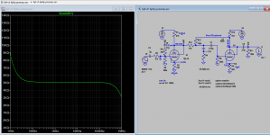
The other alternative is to bring down the gain by adding Shunt FB as in my schematics. This bring down CL gain to 5V (from 18db to 14db), distortion is further reduced.
Attachments
Last edited:
Thanks, just a question, what is R4 and the preceding capacitor doing and what would be the values?
Because the feedback resistor goes to 6J4 cathode which sits at 11vdc. You do need a cap to block that DC from leaking into the output.Why is there a 2.2uF cap after the plate of the 6V6, then the feedback take-off, and then another 2.2uF cap? I don't think that's necessary. I guess the final output sees a 1.1uF-120k ohm HPF, but the feedback loop sees the signal coming off 2.2uF, so more LF gets fed back than goes out the output(?).

- Home
- Amplifiers
- Tubes / Valves
- Preamp Circuit Advice