I reiterate that power amplifiers are meters apart from the hi-fi rack. No devices are stacked. Each of them are on a shelf.
As for potential oscillation, how to check that during FM modulation playback ?
Maybe by observing with an oscilloscope not directly the output of the preamp, but with a wideband active filter in-between the preamp and the scope to remove the audio-band. I have a filter with 20 MHz -3 dB bandwidth at hand. I will give that idea a try.
A ground loop through audio cable is possible , if two or more devices are grounded by ac power cable and outlet and metal case is not properly isolated from all rca output jacks or device internal ground. But still good question how that's related to fm only operation .
None of my devices is grounded. But I wil check the outer shield coming from the outdoor RF antenna, just in case.
Not sure that is a relevant measurement - you want to hook the S.A. to the audio output of the FM receiver while its tuned to a stereo transmission.Then, I have aligned the needle of the selective voltmeter in relative measurement mode with the 0 dB mark on the galvanometer and I have searched for the 19 kHz and 38 kHz tones with real radio stations, having being careful to tune in a station that emit a signal which do not clip the input of the voltmeter - a classical music radio station.
I have found the pilot tone bang on 19 kHz to be -57.5 dB on the left channel and -61.8 dB on the right channel. I have searched for the 38 kHz tone, but the needle barely showed a smidgen of deviation of 2 to 3 dB in the "unspecified" bottom 90-80 dB range of the galvanometer. In any case, the 38 kHz is thus way below -80 dB.
The HP 3581A was hooked to the audio output of the tuner while a stereo transmission was received. From a certain point of view, the HP is basically a manually scanned spectrum analyzer with a galvanometer showing the voltage level of single a frequency or very a narrow pass-band instead of a display showing of the entire scanned spectrum at once. I cannot see any problem with this measurement, unless I do not understand something. For that matter, the service manual of the tuner said that a selective voltmeter is the basic tool to adjust the 19 kHz notch filter and check the level of the 38 kHz.
Tonight, I tried to hook the spectrum analyzer (a basic Hameg unit, so nothing special) to the audio ouput of the preamplifier while listen to stereo radio station and CD/SA-CD with a 500 kHz high pass active filter in-between the audio output and the SA. I could clearly seen the output bandwidth of the active filter (about 30 MHz wide) on the spectrum analyzer through elevated noise floor and spurious even without anything connected at the input. Switching in the output of the preamplifier gave elevated noise floor and spurious tones in that bandwidth. There was spectral content above the bandwith of the active filter. Probably picked-up signals, I suppose. I cannot see anything special when the tuner is selected compared to when the CD/SA-CD player is selected as a source. Except I could discern the zone where the computer-control of the tuner produce some HF signals when I use the push-button of the tuner, but this signals were in the vicinity of -100 dBm, barely above the noise floor of the analyzer... But I think I would have been better off with a passive filter than the active one, which is ovisouly not very good, to eliminate the audio.
Tonight, I tried to hook the spectrum analyzer (a basic Hameg unit, so nothing special) to the audio ouput of the preamplifier while listen to stereo radio station and CD/SA-CD with a 500 kHz high pass active filter in-between the audio output and the SA. I could clearly seen the output bandwidth of the active filter (about 30 MHz wide) on the spectrum analyzer through elevated noise floor and spurious even without anything connected at the input. Switching in the output of the preamplifier gave elevated noise floor and spurious tones in that bandwidth. There was spectral content above the bandwith of the active filter. Probably picked-up signals, I suppose. I cannot see anything special when the tuner is selected compared to when the CD/SA-CD player is selected as a source. Except I could discern the zone where the computer-control of the tuner produce some HF signals when I use the push-button of the tuner, but this signals were in the vicinity of -100 dBm, barely above the noise floor of the analyzer... But I think I would have been better off with a passive filter than the active one, which is ovisouly not very good, to eliminate the audio.
I checked the output of the preamp with a scope and an high-pass filter in-between with tuner on and tune on a stereo station. I couldn't find any trace of oscillating signal, providing I have done the measurement correctly.
Astonishingly, neither the preamp or the power amp did warm-up when I made the above observation with the spectrum analyzer, despite the fact that the hi-fi system and the measurement instrument where on for at least 3 hours.
I cannot make head or tail of it. 🤔
Astonishingly, neither the preamp or the power amp did warm-up when I made the above observation with the spectrum analyzer, despite the fact that the hi-fi system and the measurement instrument where on for at least 3 hours.
I cannot make head or tail of it. 🤔
Did you played FM radio through speakers ,during these tests and measurements? If you used hi-pass filter, audio would miss low frequencies and most of power , that would explain why no heating was found. Or you filtered just input to measurement tools , or low-pass was inside tool ?
Yes ! I should have mentioned that the preamp has two parallel outputs. I have monitored one of them with the measurement set up while the other was still connected to the power amplifiers to listen to the radio. I should also point out that the ambient temperature in the room was still to +/- 0.5 C. during the experiment.
Well, perhaps i fall onto some intermittent cause.
I should also make one more precision : the outdoor antenna was installed by a third party some years ago. There are about 20 to 25 m of RG6 cable between the aerial and the indoor, plus some 5 m of indoor coax cable between the plug and the tuner antenna input, with a protection device insde a powerstrip in-between output and input cabling. I wonder if should investigate or check something about the outdoor antenna and its cabling ?
Depending on antenna size and height , probably antenna is grounded, to protect from light strike and so , but you said , none of your audio equipment is grounded, so ground loop through antenna cable should not occur.
I think heating can be related to two things - time , how long amplifier is running, and volume/content dependent, compresion etc. Power meter should tell you truth or at least partial information, maybe idle current increases after few hours , when amplfier plays a little louder.
Maybe something changes , when your measurement tools are connected? Maybe they are grounded?
So , something is getting ground ,and working as it should, when testing , and something not right, when have no ground. Can you test without ground ,just to exclude this ?
Good idea. I will whenever I find that preamp or amp warms up.
I just checked the installation manual of the same type of aerial that was installed at my home. I very much doubt that the mast and antenna were installed as recommended in the brochure I just read : https://www.farnell.com/datasheets/2365687.pdf
I never recall having seen any grounding block or ground wire.
After I have listened to the tuner with the test equipment unhooked, both preamp and the 2 power amps got warm again... And they do not got warm after I have watched a DVD another day. In both case, the hi-fi was switched on roughly the same time.
I begin to suspect the lack of grounding of the FM antenna. I have checked the regulation in my country, and the current laws mandate at least that the coax braid shield to be grounded, which is not the case in my home for some reason.
I will install a grounding block soon. Thus, I will be able to test with and without grounding the antenna cable shield. I shall also devised a test set-up to by-pass the ground on my test equipment in order to have a better look at what's going on.
Could it be some resonance forming in the antenna coaxial cable ?
Sounds strange again... Actually , RF cables have requirements to be some length , related to wave length . Maybe you have standing wave , because of unmatched cable length. But you can try to make isolation transformer from RF ferrite , to isolate antenna cable fully from tuner , and then ground antenna as required. Also you can test another method of isolation, place in series of antenna cable two capacitors , HV ceramic 1000pf , one in series with shield ,one in series with center conductor. They will brake ground loop if such exists at low frequencies . Capacitors can be placed in some models of jack , or you can solder a adaptor with male/ female RF connectors used in your tuner and antenna cable .
Actually, when your tuner is connected to preamplifier, preamplifier to amplifier , all are at same potential. And when you switched to another source like DVD or CD, shield wires and ground are still connected as i understand, just center signal wire are switched to another source. So if antenna cable catches something by it's ground wire , it must always make amplifier and preamplifier hotter . Maybe lack of rf filter in preamplifier inputs cause this?
Actually, when your tuner is connected to preamplifier, preamplifier to amplifier , all are at same potential. And when you switched to another source like DVD or CD, shield wires and ground are still connected as i understand, just center signal wire are switched to another source. So if antenna cable catches something by it's ground wire , it must always make amplifier and preamplifier hotter . Maybe lack of rf filter in preamplifier inputs cause this?
Last edited:
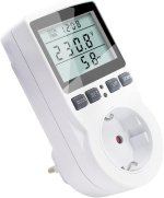
Get one of these cheap but quite usefull power consumption check thingie's you plug between power outlet and the consumer. Often found in your supermarché for around 10€.
Record the consumption over some time, in your "hot" and "cold" setting. The consumption must be higher when everything heats up, the meter gives you an idea how much.
All points to some oscillations of the tuner that the pre as well as the main amps are canceling out. On the output of the power amp usually is such a coil, resistor combination, made to prevent the speakers to burn.
Such signals have been know to kill tweeters for no obvious reason, also coils in the x-over get noticeable hot, often the plastic part of it get molten and the PCB brown.
This is not a feature of your gear but a fault, probaply due to age.
Attachments
Thank you for your advises, ximikas and Turbowatch2. I will give them a try as soon as possible.
Oscillations seems the most plausible cause. I have two other different tuners in reserve. I will try them just to verify if the problem is or not device-related.
I know that M. Hans Knoll, the engineer at Grundig who directed the design of my tuner, writes on a German website. I will try to contact him, but my German is not at all as good as my English... 😳
Try in English. No German will refuse to answer, just because you use it. In very complicated cases we use Google Translator...
If you have the schematics, these Grundig stuff is well documented, a lot o test points and test conditions, which tool used etc.
Any old style electronics engineer/ repair man should be able to repair them. That's what my long time retired repair man (Radio Techniker Meister) always told me, while calling other brands "unrepairable".
I still have an as new SXV 6000 pre amp.
Any old style electronics engineer/ repair man should be able to repair them. That's what my long time retired repair man (Radio Techniker Meister) always told me, while calling other brands "unrepairable".
I still have an as new SXV 6000 pre amp.
Last edited:
Yes, I have all the documentation about this particular Grundig T-9009 (and my two other tuners from the same brand, by the way. Love them : very good reception and able to switch to a clean stereo with very week signals).
Now for something else : I just check with a simple DMM the coaxes coming from the outdoor FM omnidirectional antenna and the satellite dish, which both use the same type of coax cable. Between hot and braid connection of the open coaxial plugs, the DMM give 0 V AC on the coax coming from the satellite dish, but about 250 to 320 mV AC with the FM antenna (no active amplifier on this line). Seems weird to me.
Now for something else : I just check with a simple DMM the coaxes coming from the outdoor FM omnidirectional antenna and the satellite dish, which both use the same type of coax cable. Between hot and braid connection of the open coaxial plugs, the DMM give 0 V AC on the coax coming from the satellite dish, but about 250 to 320 mV AC with the FM antenna (no active amplifier on this line). Seems weird to me.
Last edited:
Maybe satellite cable gets grounded through tuner and because of this you measure no potential on it ? Or sat equipment outside installed by another company and made properly ,with grounding .
Try to connect a led diode between FM antenna cable ground and mains ground (PE), if led will lit , means you have induction in atenna cable , or improper connection ,grounding or so .
Actually there always potential difference , if you measure AC N to AC PE , because any current flowing through load ,will cause voltage drop on N wire .
At another end of cable ,sometimes in circuit breakers box,or when energy meter is installed, N joined with PE and this point is grounded .Sometimes this joining is distant ,and you can measure even few volts while line load is heavy ,few kW.
Maybe FM antenna grounded ,but improperly ,by just connecting it to N mains wire somewhere outside , or to water or gas pipe ? If so ,thats very unsafe, if mains cable N fails somewhere ,it can get full mains potential through connected load .Also water or gas pipes are long and can catch various frequencies like antenna ,bad idea of grounding .Better recheck . Also possibly , antenna cable is installed very close to mains cable long distance and current through mains cable causes induction in antenna cable .
- Home
- Source & Line
- Analogue Source
- Preamp and amps getting warmer when listen to FM tuner