2 stage adjustable gain as volume control
Designing a Op-amp line level pre-amp is mostly based on a first amplification stage, volume pot and buffer.
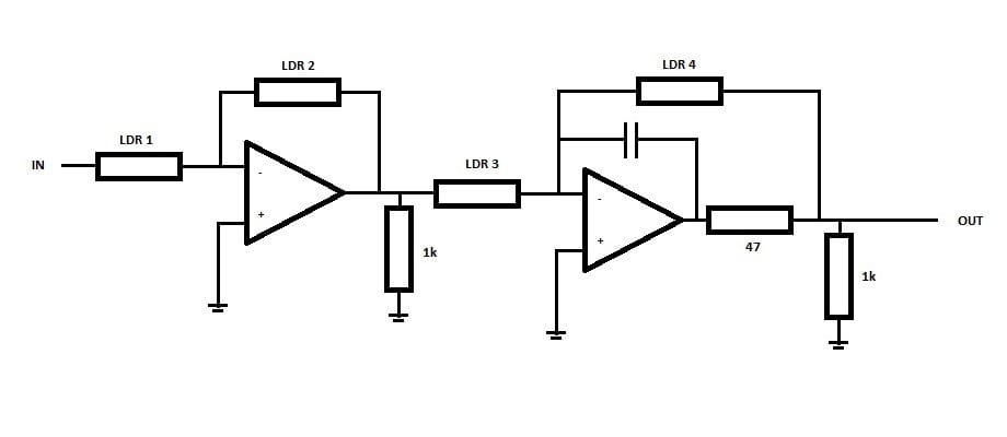
I am looking into building a pre-amp but with LDR resistors replacing the volume pot.
I know about the variation in LDR curves but will solve this by a programmable controller driving the LED’s having a well-defined resistor curve.
Thinking about the options about using “adjustable” resistors I had the idea why not use it to adjust the amplification instead.
Having a single stage going all the way down to -60 / -70 dB requires very careful selection of LDR’s.
What about using 2 Op-amp stages which both are adjustable ?
Going -35 dB per stage ( = approx.. 1/56 resistor ratio) would give -70 dB as full range.
FYI: the Op-amps will be discrete built Opamps with Class A output able to drive >10 mA in Class A.
With modern line level components of 2V out and a power amp only needing less for full power I need attenuation instead of amplification.
Looking at my design I realise LDR1 can probably be replaced by a 100k resistor but being able to adjust the load to my sources for evaluation might be beneficial.
I can also set it source dependant ;-)
What is your take on my design ?
Should I start regulating LDR2 as primary control and have LDR3+4 equal as a 1:1 buffer and as soon as I want more than 35 dB attenuation start regulating LDR3+4 for additional attenuation ?
And maybe I am overlooking some other complications ?? Of even a complete design flaw ?
Any input from you (the experienced guys) is highly appreciated.
Thanks in advance.
Designing a Op-amp line level pre-amp is mostly based on a first amplification stage, volume pot and buffer.
I am looking into building a pre-amp but with LDR resistors replacing the volume pot.
I know about the variation in LDR curves but will solve this by a programmable controller driving the LED’s having a well-defined resistor curve.
Thinking about the options about using “adjustable” resistors I had the idea why not use it to adjust the amplification instead.
Having a single stage going all the way down to -60 / -70 dB requires very careful selection of LDR’s.
What about using 2 Op-amp stages which both are adjustable ?
Going -35 dB per stage ( = approx.. 1/56 resistor ratio) would give -70 dB as full range.
FYI: the Op-amps will be discrete built Opamps with Class A output able to drive >10 mA in Class A.
With modern line level components of 2V out and a power amp only needing less for full power I need attenuation instead of amplification.
Looking at my design I realise LDR1 can probably be replaced by a 100k resistor but being able to adjust the load to my sources for evaluation might be beneficial.
I can also set it source dependant ;-)
What is your take on my design ?
Should I start regulating LDR2 as primary control and have LDR3+4 equal as a 1:1 buffer and as soon as I want more than 35 dB attenuation start regulating LDR3+4 for additional attenuation ?
And maybe I am overlooking some other complications ?? Of even a complete design flaw ?
Any input from you (the experienced guys) is highly appreciated.
Thanks in advance.
Last edited:
I don't think you need to adjust LDR1 and LDR3 at all; they can be fixed resistors. You can vary LDR2 and LDR4 at the same time, which should ensure you have maximum headroom at all times. (You could then put your two LEDs in series, which would simplify the MCU code.)
Last edited:
You are right ... LDR 1 and 3 can probably be replaced by fixed resistors.
But being ale to try several resistance combinations are now available through software ;-)
Also limiting Johnson noise at normal listening volume I better start with a relative low resistance for LDR1 and 3 to for example 10k which should be o.k. as input sesistance for the source and only increase when a higher attanuation is needed and the feedback LDR is already close to its lowest "safe" possible restance value.
Putting 2 LED's in series will only work best if you have both with the same curve ... which probably will not be the case.
Adjusting the gain of an opamp with the NFB loop changes the stability margins.
It is not a good idea.
If you can change the compensation to suit each gain so that the stability margins remain the same for each new gain setting, then the amplifier performance will be more consistent.
eg.
a unity gain opamp with the gain set to 1 often has a specified phase margin of 45°.
Change the gain to +20dB and that phase margin could move to 68°, or for a gain of +30dB could be around 80°.
Those three gain settings with the attendant different phase margins will sound very different !
- Status
- Not open for further replies.