Additional Note, i had been using 3.9ohm load across the terminals during test, and replaced them with some speakers, now the temps have dropped to ~33C with that easier load.
Good deal, sounds like it's under control. With two chips running in parallel you'll be able to drive loads as low as 2 ohms in theory, and of course it depends on how efficient the heat sink is. Have fun!
Mike
Mike
cheers mate. I've just tested the DC offset of a couple other retail amps i've bought, and they are measuring +15mV on each channel, i too have adjusted those down to ~0 fairly easily enough. Thanks everyone for the direction and advise, i'm sure i'll be here soon asking a few more questions.
rick
rick
Richard, I have two of these - one working at 17VDC on all three chips. The other one is producing some oscillation that makes the DC readings fluctuate wildly. I couldn't tell from your posts if you actually installed the 100K pots and/or added a second surface mount resistor.
I bought the boards only from Jim's Audio on eBay and he sent a diagram.
I'm going to do the two chip mod and hope I get as good results as you.
I bought the boards only from Jim's Audio on eBay and he sent a diagram.
I'm going to do the two chip mod and hope I get as good results as you.
Last edited:
Hi bob,
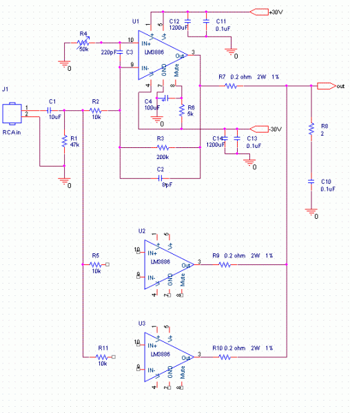
thats the very same amp circuit i have, one thing i can see that is different is the C1 capacitor. On that schematic it's rated at 10uF, i have a 4.7uF used on my board. I had removed the centre chip from each board to make lowering the DC offset abit easier and stable to adjust and maintain between the chips. There was too much varience between three chips that was unable to be controlled.
One thing i have observed during warm up, warm down is, what ever change in DC offset one chip has, it is countered on the other. So now i would recommend replacing those 50K pots to 100K, i havn't done it yet, but my guess is that a higher range pot, you may get more stable and tighter DC offset.
And whats this oscillation problem your seeing? i'm assuming your talking about the phase between the two?
rick
Last edited:
- Status
- Not open for further replies.