Hi All
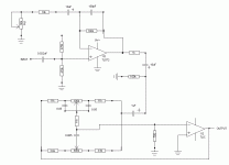
New user, first post. I have built the attached circuit, cobbled together from the pre-amp in "The Guitar Handbook" and a tone control from somewhere on the internet.
The pre-amp works fine (if I isolate it), but the tone control kills all the volume and does not really alter the tone at all.
I am very new to this, but I guess the tone circuit does not match up with the pre-amp? Maybe it is designed for a much higher voltage? Not sure, but I do know that there is no problem with the pre-amp, but that the tone control side must need a lot of work.
Do I just need to alter the values on the resistors, pots etc? Does anyone have any suggestions as to what values I should use?
Any suggestions would be appreciated. Even if the suggestion is "just use Brion55's design......"
Cheers
Attachments
First with inverting configuration you don't need the Rin, and a 750 ohm Rin is definitely too small anyway.
See if you need to do anything else, this should fix it. Normally circuits of this type have an AC feedback loop through the control area (using decoupling capacitors) and a separate DC feedback loop, usually in non-inverting configuration, like a standard opamp. But this one should work too, just remove the 750 ohm resistor.
See if you need to do anything else, this should fix it. Normally circuits of this type have an AC feedback loop through the control area (using decoupling capacitors) and a separate DC feedback loop, usually in non-inverting configuration, like a standard opamp. But this one should work too, just remove the 750 ohm resistor.
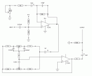
The 1k resistor / 10uF cap / 100k resistor network on the output of the preamp section does short protection / DC isolation / DC ground restore and is not required between the preamp and tone circuit - move it to the output of the tone control section, so that the 1uF cap joins the two sections.
As sangram said, remove the 750 ohm resistor - it is not required. The non-inverting input of the tone control opamp should also NOT go directly to ground - it needs a 1/2 voltage reference point. Use two resistors, one to ground, one to +9V of say 470k like the preamp section has, and put a 10uF cap across the bottom resistor. I would also lower the value of the two .05uF caps to .022uF (22nF) and reduce the value of the treble pot to 100k.
Cheers
Graeme
Still needs the resistor divider on the non-inverting input of the second opamp !!!!
Cheers
Graeme
Cheers
Graeme
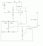
Sorry. Did not fully revise the circuit with the non-inverting side mods for the tone section. Here is the revised revised version.
Graeme:- When you say "and put a 10uF cap across the bottom resistor", which one is the "bottom resistor?"
Cheers
Graeme:- When you say "and put a 10uF cap across the bottom resistor", which one is the "bottom resistor?"
Cheers
Attachments
That's better. Put the 10uf cap +ve to junction of these resistors, and -ve side to ground - this will prevent hum pickup by the opamp's non-inverting input.
Cheers
Graeme
edit: and just noticed, reverse the polarity of output capacitor
Cheers
Graeme
edit: and just noticed, reverse the polarity of output capacitor
Yep, should work well.
On another note, if you want to conserve battery life, use the TL062 low power opamp.
Cheers
Graeme
On another note, if you want to conserve battery life, use the TL062 low power opamp.
Cheers
Graeme
Hi Brion55
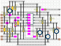
I saw your schematic, and am definitely interested in building it. The only problem is that it will take me about a week to work out how to get the schematic onto veroboard (see attached for how I am intending to handle the circuit as discussed in this thread). If you have a layout, that would be a life (or at least time) saver.....
Also, as posted on another thread, I was wondering about using your design either with a pot on the pre-amp in order to have variable gain, or alternatively having two different gain settings which are switchable.
If I used a pot, I would build your two band eq model. If I used a switchable two gain level version, I would probably go for the three band version.....
Cheers
Attachments
- Status
- Not open for further replies.
- Home
- Live Sound
- Instruments and Amps
- pre-amp and tone circuit. Help needed...


