Hi everyone;
I was just working on this, and wanted to get some inputs prior to fabbing PCBs and buying parts.
This is a practice amp with the following features
- 4 x AA NiMh batteyr pack
- DC power jack on rear
- 50mA constant current charge using LM317L
- Charge and Power LEDs
- 1/4 mono input
- adjustable from clean to dirty, using simple diode clipper
- modified tone stack with bass and treble adjustment +/- 8dB
- Volume goes to 11
- headphone jack 3.5mm which disables the speaker
- LM4861 boomer driving 4" 8 ohm speaker, about 1.2W
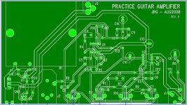
The below pic is one layer, the oppostie is 100% poured copper ground
I was just working on this, and wanted to get some inputs prior to fabbing PCBs and buying parts.
This is a practice amp with the following features
- 4 x AA NiMh batteyr pack
- DC power jack on rear
- 50mA constant current charge using LM317L
- Charge and Power LEDs
- 1/4 mono input
- adjustable from clean to dirty, using simple diode clipper
- modified tone stack with bass and treble adjustment +/- 8dB
- Volume goes to 11
- headphone jack 3.5mm which disables the speaker
- LM4861 boomer driving 4" 8 ohm speaker, about 1.2W
The below pic is one layer, the oppostie is 100% poured copper ground
Attachments
"These amps go to 11....." nice touch......😀
IIRC Crate did that for a while....
one practice i picked up many years ago that you might want to consider. put the dropping resistor for the power LED on the high side of the diode. that way if for some reason the LED leads touch the grounded case (such as might happen during testing the unit while partially disassembled), the LED won't get burnt out.
Nice circuit. I'm a bit nervous about that BYP divider point not being buffered. It's well bypassed, so should be ok for ac, but will there be any problem with the feedback ratio on the distortion amp? I'd also consider the charger circuit- I'm too impatient to use a safe value of constant current charge, but at higher currents you really need a cutoff so it goes into float mode. If the input voltage is just right, it would work ok, but maybe consider one of the cheap battery charger chips. That way you could use NiMH cells to maximum advantage (they don't really like trickle charging).
Uncle Jed - excellent suggestion. Not a big issue on this design, as I am using the dual diode in one black block thingie. I usually do it the way you suggest, but never for any particular reason.
Conrad - good call. Every single battery charger IC I have ever seen was SMT. It's not that I am afraid (see www.minthesizer.com), but the board is 100% through hole at this point.
I thought I could easily add a TL431 as a shunt, but then read more on NiMH, not a good idea. MAX713 is the closest to easy, but even that is a 50% increase in the total circuit complexity.
So I have an easy solution: NiCd batteries. Not very sexy, but they should do the job.
On the unbuffered ref, the worst case current is about 2V on 10k, or 200uA. Into 10uF, this would be about 20mV ripple at 100Hz. Also, the BTL amplifier output will reject this ripple.
Thanks again for your inputs. Your reponses show you really spent some time looking at this. I'll post here when I get results later.
you could use a MOSFET to cut off the charging current. or you could use Lead-acid gell cells and use the circuit you have. a small gel cell (like the batteries that were used in the carry packs for motorola brick phones) will power the amp for about 10 hours per charge, and don't weigh very much.
Hi,
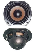
Careful selection of the speaker will make a big difference.
As it will be small a sealed cabinet should be used.
Possible candidates :
http://www.partsexpress.com/pe/showdetl.cfm?&Partnumber=290-010
http://www.mcmelectronics.com/product/54-310
http://www.mcmelectronics.com/product/55-1595
http://www.mcmelectronics.com/product/55-1205
(published response of this one is "guitar speaker" like)
If you do not go for any of the above I'd suggest finding
a high efficiency paper TV type speaker, something like :
http://cpc.farnell.com/LS00464/audi...sku=unbranded-59-l12-01-51f&_requestid=542775
🙂/sreten.
RDV said:
Hi,
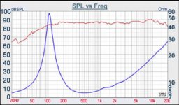
That driver has a dip where you ideally would like a peak for guitar.
The dip is down to 80dB/W, in reality the driver is ~ 85dB/W.
This is why I did not include it. Tested by Zaph at Zaphaudio.com.
🙂/sreten.
wow, I'm not the only speaker guy
Thanks for the driver suggestions. I am going for a bit lighter and portable, so going to use a 3" Tangband driver, most likely. I will use whatever is in my drawer first though before canibalizing a tangband out of an existing computer speaker pair.
Thanks for the driver suggestions. I am going for a bit lighter and portable, so going to use a 3" Tangband driver, most likely. I will use whatever is in my drawer first though before canibalizing a tangband out of an existing computer speaker pair.
Attachments
Hi,
FWIW hi-fi drivers make poor guitar speakers. Like I said :
"Careful selection of the speaker will make a big difference."
Your best bet really is a old TV speaker - because they are so poor.
The older ones are designed for low power. They have a distinct
presence boost to maximise sensitivity and loudness capability
for speech, in use the TV applies bass boost to even things
out somewhat - they do make passable guitar speakers.
The TB sensitivity figure is fiction. A Fostex/similar 3" is more
sensible. This has no excursion but for 1 watt you not need it.
All the 3" TB types tested by Zaph are under ~ 83dB/W.
Related to sensitivity is size, generally the bigger, the more you get.
If something like the above 4" does get over 90dB/W with only
1W on tap this will work far better than a long throw small driver.
🙂/sreten.
FWIW hi-fi drivers make poor guitar speakers. Like I said :
"Careful selection of the speaker will make a big difference."
Your best bet really is a old TV speaker - because they are so poor.
The older ones are designed for low power. They have a distinct
presence boost to maximise sensitivity and loudness capability
for speech, in use the TV applies bass boost to even things
out somewhat - they do make passable guitar speakers.
The TB sensitivity figure is fiction. A Fostex/similar 3" is more
sensible. This has no excursion but for 1 watt you not need it.
All the 3" TB types tested by Zaph are under ~ 83dB/W.
Related to sensitivity is size, generally the bigger, the more you get.
An externally hosted image should be here but it was not working when we last tested it.
If something like the above 4" does get over 90dB/W with only
1W on tap this will work far better than a long throw small driver.
🙂/sreten.
Hi
The LM4861 boomer chip is only available in SOIC, but yer layout is DIP.
Definately take advantage of the shut down feature of the LM4861 to save the bat from draining down. Perhaps using a 3 or 4 way jack on the guitar input plug.😉
Look for the highest sens. speaker you could find with a highish Qt for an open back cab. Raid an old portable radio perhaps.
Cheers
LM4861 DIP
Infinia - That is a VERY good catch. Actually, I already knew that, but it just so happens I do have a number of the devices in DIP package anyway. Don't ask me how ;-)
On the speakers, I do have some 4" TV speakers with bucking magnets. These might be too linear. They were close-outs at Parts Express a number of years ago, but you can still find data on them here...
http://ratch-h.com/69centwonder.html
and pictures here:
http://www.minthesizer.com/cheapspeakers.html
SMT: in for a penny.....
in for a pound
I switched the entire design to SMT where possible, and shrank the board. Size is now 4.3" x 2.1"
most of the space was saved by moving batteries to the PCB bottom, and changing to AAA size. SMT helps a bit too!
I need to pick a speaker to match. THis will be getto, for sure, but I am going fo ra cute (did I just say cute?) little practice amp. Kinda an exrecise in how small it can be made and retain functionality.
Attachments
i recently saw a Marshall practice amp....... a little chip amp that looks like a 8 inch high marshall stack...... gave me an idea for an Ampeg Flip-top lookalike using submini tubes... won't be as small, but it will be a 1 or 2 watt itsy-bitsy tube amp..... if i could find a few round 8-pin opamp sockets for the tubes that would be nice.... i already have a few submini power pentodes and a few dual triodes. i will need a small output transformer and a small 50V-100V power transformer. these tubes are about 1/2 the size of a 12ax7, so you can get in idea of the scale factor. it will be about the same size as most practice amps, about a foot square and 6 inches deep, with the amp chassis mounted on top
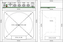
Mechanical Mockup
I sent for PCBs this weekend, they're 4.3" x 2.0".
I was waffling on how to build an enlosure..
- Make a min faux Marshall stack
- use tweed, or perhaps wrinkle paint
But I think I will use 1/4" plexi, as the finishing is not necessary, and all the guts are visible to behold.
I will put the battery pack in the bottom, it helps lower the CG for stability, and one less thing to confuse the PCB
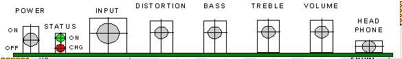
There is no front bezel, per se. The PCB is silked for the dist./bass/treb/volume functions, and will be visible from the top through the plexi.
I sent for PCBs this weekend, they're 4.3" x 2.0".
I was waffling on how to build an enlosure..
- Make a min faux Marshall stack
- use tweed, or perhaps wrinkle paint
But I think I will use 1/4" plexi, as the finishing is not necessary, and all the guts are visible to behold.
I will put the battery pack in the bottom, it helps lower the CG for stability, and one less thing to confuse the PCB
There is no front bezel, per se. The PCB is silked for the dist./bass/treb/volume functions, and will be visible from the top through the plexi.
Attachments
you might want to put a few beads of clear RTV across some of those panels to dampen vibration. plexi will resonate, not as bad as glass or metal, but it's not as "quiet" as wood either.
questioning the status quo
Hi Uncle Jed;
I often do what I am told not to do!
See the below link
http://www.geocities.com/thespeakerguy/anatomypic1.html
Suprisingly, this did not resonate, but there is a hole in the response, never did try to debug. They are used as garage speakers.
Anyway, I will likely use maple or pine, with a clear finish. Ends up my supply of plexi is low.
- Status
- Not open for further replies.
- Home
- Live Sound
- Instruments and Amps
- Practice Amplifier