I'm working on a project based on Fisher 500B iron, and wanted to go simple. I found this article a while back, and it looked like great information:
Practical Phase Inverters.
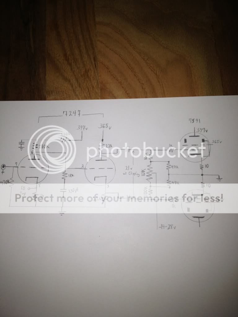
The 7247 scheme says it will drive a pair of PP 6l6 tubes to 26W. I tapped off of my PS at a 385V point because tapping at the 400V point was noisy due to the plate currents of my 6l6 tubes.
To my dismay, I got a horrible response from this scheme until I started trying various values of coupling caps. I now have .68uf coupling caps along with some feedback and get clean sines down into the 20s, but this circuit only drives about 31V rms from grid to grid with 3.5V in which is way too little to drive the 6l6 past about 10W.
Is there any way to get a bit more gain out of it, or should I just rewire the output section for 7591 tubes to take advantage of their higher gain?
Thanks!
Blair
Practical Phase Inverters.
The 7247 scheme says it will drive a pair of PP 6l6 tubes to 26W. I tapped off of my PS at a 385V point because tapping at the 400V point was noisy due to the plate currents of my 6l6 tubes.
To my dismay, I got a horrible response from this scheme until I started trying various values of coupling caps. I now have .68uf coupling caps along with some feedback and get clean sines down into the 20s, but this circuit only drives about 31V rms from grid to grid with 3.5V in which is way too little to drive the 6l6 past about 10W.
Is there any way to get a bit more gain out of it, or should I just rewire the output section for 7591 tubes to take advantage of their higher gain?
Thanks!
Blair
That's probably not optimal for 6L6, which take a reasonable amount of voltage drive. A long tail pair would be a better choice, with the cathode CCS taken to a negative rail.
When someone says that they want to "improve" on a 6SN7 because it's a 50 year old tube, take anything else they say with a grain of salt- it's a superbly linear tube, and the Williamson circuit is still among the best ever front ends (once the LF coupling problem is cleaned up). The distortion numbers quoted in the linked article are not inspiring and can easily be bettered.
For a superb and comprehensive survey of phase splitter options, see Crowhurst's "Understanding Hifi Circuits." As well, Morgan Jones does an in-depth analysis of the LTP and cathodyne in "Valve Amplifiers," but limits his discussion to those options.
Hi SY,
Right. I have used the williamson circuit in many applications and agree with you there.
I wasn't necessarily trying to get "improved", but rather a simple little amplifier that fits in a small chassis.
The 31v grid to grid I get out of this clean should be enough to drive the 7591 right?
Are there any other tubes that have that high of gain in an 8 pin bottle? The EL34 would be OK I suppose. But I do not have the heater requirements for it in my power transformer.
Thank you,
Blair
7591, 8417 (which is problematic on many levels), EL34. Can't think of too many other options in octal. If you can stand some 9 pins, a quad of EL84 can get you 50 watts or more and they're super easy to drive.
Are there any other tubes that have that high of gain in an 8 pin bottle? The EL34 would be OK I suppose. But I do not have the heater requirements for it in my power transformer.
If you had the heater current, the octal-EL509 would be your choice. Thanks to the high gm, the drive requirements are minimal.
Just have a look at the curves and compare what a few volts on the grid can do:
http://www.jj-electronic.com/pdf/EL 509 .pdf
http://www.jj-electronic.com/pdf/6L6 GC.pdf
One of the most underrated tubes out there.
I finally got around to requiring for 7591, and it sounds great with the exception of the drive voltage into the output stage.
I only get 21V before my sines start clipping at the input grids on the 7591 resulting in a max output of around 10-12W. I thought it might be the feedback, but after clipping it out, the issue is at the same driver output voltage.
Any suggestions to improve the drive voltage?
The article I referenced for the schematic stated that it would drive 6L6 tubes to 21W.
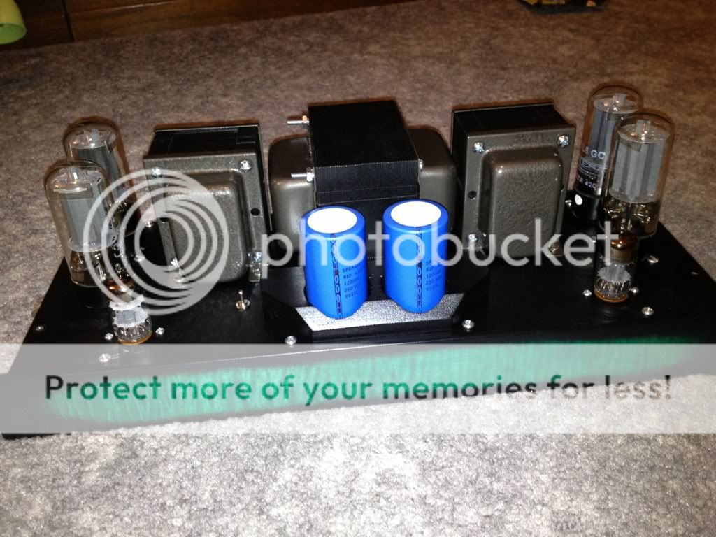
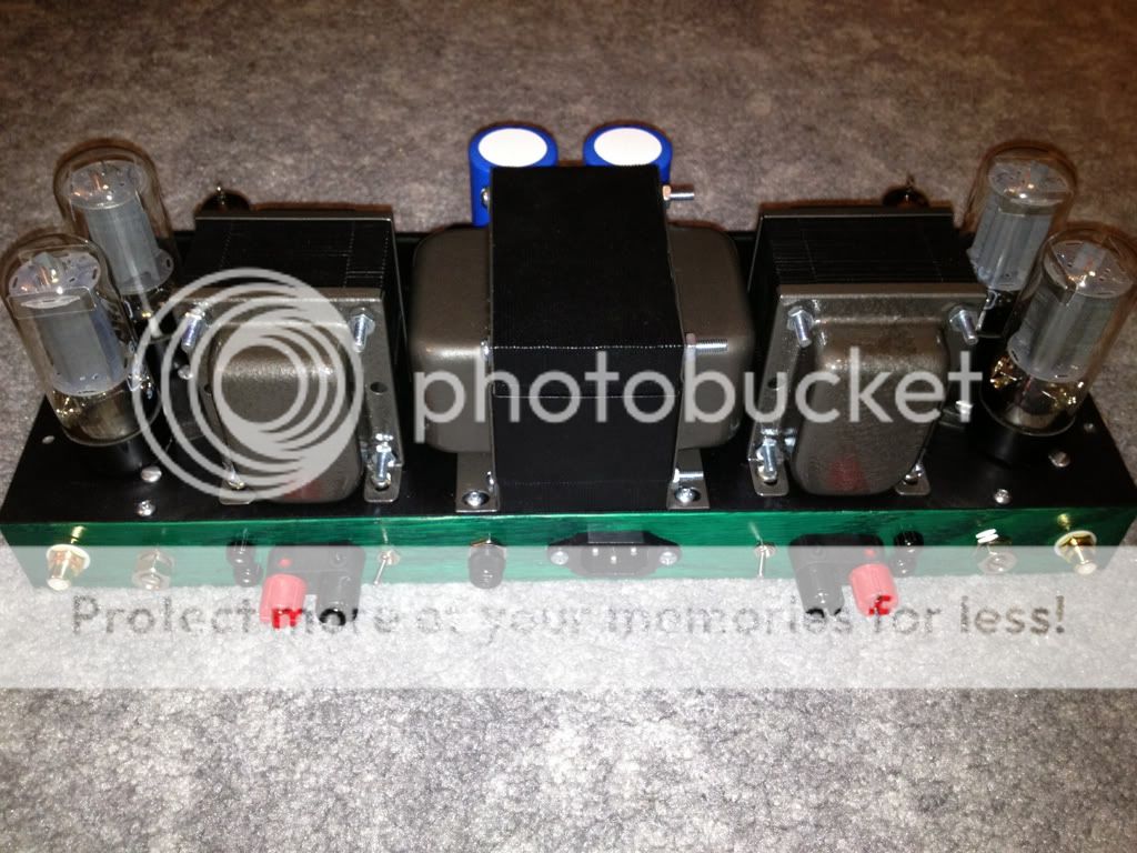
On another note, this was all put together for fun, but it has become fairly distracting from my other projects. If anyone is interested in this for a reasonable price, PM me:
Thanks!
I only get 21V before my sines start clipping at the input grids on the 7591 resulting in a max output of around 10-12W. I thought it might be the feedback, but after clipping it out, the issue is at the same driver output voltage.
Any suggestions to improve the drive voltage?
The article I referenced for the schematic stated that it would drive 6L6 tubes to 21W.
On another note, this was all put together for fun, but it has become fairly distracting from my other projects. If anyone is interested in this for a reasonable price, PM me:
Thanks!
Take out the output tubes and measure the voltage where the phase splitter clips. You clipping may be (probably is) the point at which the output stage is drawing grid current, not a driver limitation.
Take out the output tubes and measure the voltage where the phase splitter clips. You clipping may be (probably is) the point at which the output stage is drawing grid current, not a driver limitation.
SY,
Given the compactness of that setup, installation of PowerDrive seems not feasible. Perhaps increasing the value of the 7591 grid "stoppers" to 15 KOhms or an even larger value is the best practical tweak.
Eli, that's not where I was going with that question, merely guessing that the limitation is in the output stage, not the driver.
...I only get 21V before my sines start clipping at the input grids on the 7591 resulting in a max output of around 10-12W.
Any suggestions to improve the drive voltage?
Thanks!
Please tell us what is the dc-voltage at the anode and cathode of the phase splitter.
Suggestion to improve drive voltage? Change the dropping resistor to the first stage from 150K to 15K and give yourself some more voltage there. You have an amplification factor of 100 in the first stage you should have plenty of room there to drive a 6L6 or similar.
The phase splitter is biased directly by the anode voltage of the amplifier stage.
If this voltage is too high, then the clipping can take place at too low AC-voltage levels.
I recommend some measurements and analysis instead of changing components randomly.
If this voltage is too high, then the clipping can take place at too low AC-voltage levels.
I recommend some measurements and analysis instead of changing components randomly.
Oops missed the direct coupling.
The way I see it then, looks like you only have about 0.65v on g1 of the first stage..thus the clipping so you can bypass the cathode of the first stage for more gain or looking at the tube curves use 120k as dropping, 330k as anode and 1.5k as cathode you still should have about 120v to section 2. This should give you a tad over 1 v on g1 of section 1 and a bit more room before clipping. I don't see anything else you can do and keep the direct coupling.
Anyone else??
Hi Guys,
Here are the voltages:
7591:
P-408V
S-368V
G- -14V
7247:
1 - 265V
3 - 103V
6 - 95V
8 - .737V
I chose the 7247 because of the referenced circuit. I originally wanted to use 6L6 because I had them.
After not getting much out of the 6L6 tube, I decided to rewire for 7591s because they are easier to drive. This led me here.
The original circuits for this transformer bundle from Fisher used a very similar configuration, but with a 12AX7 in both phase splitter and amplification duties. The Fisher spec'd the 7868/7591(similar) as to put out roughly 20W continuous.
It would be nice to at least get in the ball park.
Thank you!
Blair
- Status
- Not open for further replies.
- Home
- Amplifiers
- Tubes / Valves
- Practical phase inverter article