Interestingly the PCM1794A data sheet recommends NE5534 for I/V and LT1028 for difference amplifier. Of course that was 10 years ago so they would probably recommend some modern superbling 8 legs now.
I think you mean there is something that WAS solved, a long time ago.
Nope.
I think you have read more into my ARTA suggestion than you should have. All I was saying was that if there was really a large change to the audio signal, not necessarily related to just the HF roll off, then you should be able to measure it. The test results that I sent you, shown in post #304, were merely an example of what I was able to easily measure, not a recommendation of what you needed to measure to decipher the effect of your mod....is going to hand-make a 1-bit impulse stimulus file that he feels could be used to come up with a lot of data that can be analysed. Wouldn't it be great if something shows up in that data?
The 1-bit impulse *.wav file isn’t some sort of silver bullet that is guaranteed to lay bare the effect of your proposed mod on the signal. It was just a convenient way to capture the CD/DAC player’s impulse, frequency, and phase response (see attachment). From the discussion that followed post#304, the consensus seemed to be that something like the two tone test would be more likely to show what is going on. ARTA, or some of your other test equipment, can be used to generate that type of *.wav file. In any case, I will send you a set of six 1-bit impulse *.wav files (0dB, -3dB, -6dB, -12dB, -24dB, -48dB) for you to experiment with. If anybody else happens to be interested in them, send me a PM.
As I mentioned before, I am not well versed in DACs or testing there-of. This topic piqued my interest mainly because it surfaced soon after I had measured several different CD player reconstruction filters. Having seen how easily ARTA measured large differences for filters that sounded to me, subtly different at best, I recommended you try measuring. I remain puzzled as to why you wouldn’t have done that immediately after noticing what you felt was an unexpected improvement. How else could you hope to understand and fully exploit the possibilities?
Attachments

Because I was more intrigued that doing something this 'silly' should have any effect at all. I demonstrated it to others, they too loved what it did. Then discovered something just as weird, that it has a sudden onset, like turning on a switch - as Ken said, in as little as 0.2dB. I knew instantly this was beyond me to find out at this stage, but since it sounded to good and so right, I didn't hesitate to use it, and maybe later get help to figure out what was going on. So I went public with it, not without a certain amount of angst, but thought it worthwhile. Others were pressing "Joe, you should make a lot of money from this" and another, a scientist friend, said "Joe, people like you discover these things, then it's up to us scientists to figure out why." What she said sounded rather logical, but it seems others can't see that.
It's not really that complicated.
And it makes great DIY, so put a lot of effort into making that part of it possible as Post #1 to 6 shows.
I hope that that sudden onset can be captured (near -1.0dB to -1.5dB) - and that it basically comes down to finding the right stimulus. As I have said, it's all at my risk, everybody can just sit back and watch me fail. But I have an advantage over them - I don't have a big ego. 😀
Cheers, Joe
PS: 2AM here.... zzzzzz....
Last edited:
Then discovered something just as weird, that it has a sudden onset, like turning on a switch - as Ken said, in as little as 0.2dB.
I hope that that sudden onset can be captured (near -1.0dB to -1.5dB) - and that it basically comes down to finding the right stimulus.
Good, the claim is repeated as I remember. I hope Joe is using 1% capacitors otherwise it must be a pain to stop, adjust the R, and listen for the sudden change.
Good to see they know how to copy.
From memory, a 50MHz (unity gain frequency) opamp with a 1k feedback resistor will produce a 'virtual ground' at its input which looks like a 3uH inductor. So the circuit behaves like a 3uH inductor followed by an integrator - thus giving a flat frequency response. Put a small cap across the 1k and this has the effect of putting a low value resistor in parallel with the inductor - maybe a few ohms.scott wurcer said:I doubt we need to go there. A good start would be to write down the system function for an op-amp I to V with a cap across the input. The op-amp can be a first order integrator with a unity gain frequency, the LM4562 shown is ~55MHz. The simple second order equation tells you a lot about what's going on including the nearly 200X noise gain at 20kHz. It's only simple algebra that's needed, but every op-amp will give a different answer.
Now add Joe's cap and resistors. You get a low pass, but perhaps with an ultrasonic peak before the rolloff as the cap and inductor form a low Q parallel resonance. Maybe the 'sudden onset' relates to having enough capacitance to shift the resonance low enough that it is sufficiently well damped not to peak. (Ooops, I nearly typed 'peek'!)
Sorry, I am introducing science into an audio discussion.
Sorry, I am introducing science into an audio discussion.
The Jcap has the two 3R3 Ohm resistors in series which rolls the stimulus off since at 20K the virtual ground is pretty good. For curiosity sake I pulled out a full top level op-amp file and yes the given values behave basically as stated.
BTW what do folks that want to play hi-rez 192k files do?
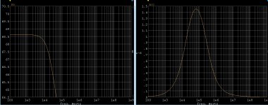
OK here's a picture using an ordinary 100MHz op-amp on a similar process. This is a full top level circuit file of one of our older amplifiers. The output is using a 2700 Ohm resistor so it is scaled by 20*log10(2700). The response is ~-1.5dB at 20k and there is no misbehavior in the frequency response.
The noise is in nVolts/rt-Hz which is my problem the integrated noise blows away the spec on any of the DAC's mentioned and it can't be filtered out (at least the part below 20k).
The noise is in nVolts/rt-Hz which is my problem the integrated noise blows away the spec on any of the DAC's mentioned and it can't be filtered out (at least the part below 20k).
Attachments
Back on track, it seems we now have at least 3 references over the last 20 years (without even trying hard) that show a capacitor across the inputs of the I/V converter. So safe to say this is a well known technique in this application amongst those well versed in the art? And certainly nothing new or revolutionary in DAC design.
Yep, I am being silenced.
Not at all, just showing your 'cap' is nothing new. It's last century.
- http://www.diyaudio.com/forums/digital-source/221743-testing-pcm1794-8.html#post3318569the pcm1794 a fft from this circuit
Practical Implementations of Alternative colour of the sky on a clear day
We are rally do progress, I may admit...
We are rally do progress, I may admit...
Last edited:
Practical Implementations of Alternative colour of the sky on a clear day
We are rally do progress, I may admit...
#706-#708 good examples of possible mechanisms, totally ignored by Joe and others for more helpful mewing's about how hard life is...
- Status
- Not open for further replies.
- Home
- Source & Line
- Digital Source
- Practical Implementations of Alternative Post-DAC Filtering