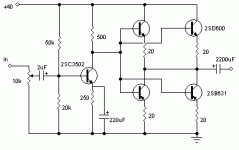
I threw this design togther, but parts are probably wrong. (I'm a tube guy, after all.)
The 2SB631 & 2SD600 are complementry.
ratings are: 100v, 1amp.
the 2SC3502 is 200v, 100mA. they are all TO-126 packaged
Let me know what you think. I can find the datasheet for the output transistors if you guys need them..
Thanks
The 2SB631 & 2SD600 are complementry.
ratings are: 100v, 1amp.
the 2SC3502 is 200v, 100mA. they are all TO-126 packaged
Let me know what you think. I can find the datasheet for the output transistors if you guys need them..
Thanks
Attachments
A note to Colt45, the 2SB631 is upside down in your diagram, it won't work with the collector being positive in comparison to the emitter...
EDIT: also, you need to bias the output transistors or you'll have ugly crossover distortion.
EDIT: also, you need to bias the output transistors or you'll have ugly crossover distortion.
Duo said:A note to Colt45, the 2SB631 is upside down in your diagram, it won't work with the collector being positive in comparison to the emitter...
oops

EDIT: also, you need to bias the output transistors or you'll have ugly crossover distortion.
how?
PS: did you get unpacked yet? 😀
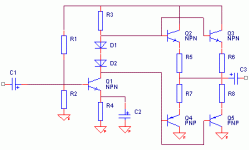
Try to re-arrange your schematic to look like that of dh's. The Diodes in the schematic are for biasing the OPS. 1N4148's should work fine. You could also use a Vbe multiplier (tansistor and pot) for more control and better sound, but play with the diodes first. You should be able to mock this up pretty quick on a breadboard and tweak the biasing to get a good sound.
what you should end up with is something similar to:
-D.
what you should end up with is something similar to:
-D.
Attachments
Okay, I see that Dozuki has successfully demonstrated a possible biasing scheme for you. This is to keep the transistors in conduction so that they don't turn off when the signal goes between +0.7 volts and -0.7 volts, in other words, crossover. Basically, one transistor is supposed to turn off after the signal has turned the other one on, but not before, this way the gap is filled and there's no crossover distortion. Each diode drops about 0.7 volts, this means that accross the two you'll get 1.4 volts which is just the right amount to turn both transistors on barely. The resistors from the + and - rails to the diodes are to keep the diodes themselves biased and provide the current that will end up biasing the output transistors. I hope this explains what we have shown you...😉
- Status
- Not open for further replies.


