Hi guys,
some days ago I purchased a Precision Power PPI 2050m black series, rev.A. It looks very fine, external and internal are in superb conditions, it seems nobody ever repaired it. I turned on the amp: left channel sounded loud but very bad, with scratching and alternator noise. Right channel sounded very very low. I replaced all electrolytic caps with new ones. Now Left channel sounds very good, but Right channel is still very very low. The 10kohm potentiometer is good. Mosfets P25N05 are ok. Transistors 2N6487 and 2N6490 are good too.
I checked resistors, they are ok and conducting on the board. But I tell you this: the previous owner used it in bridging mode with a subwoofer, but he had a mistake in wiring because he had not the molex connector. So he used +left and +right, connecting to 1st and 4th pin on the output ( 5th is remote turn on). As you know, 2nd and 4th are common in PPI, so he loaded just the left channel and had no load on the right channel. I know this is non good for amps. Have anybody idea about this issue? Many thanks to everyone will help me."
It doesn't hurt an amp if you don't use all channels.
Have you pulled to muting transistors to see if that's where the signal is being lost?
Have you pulled to muting transistors to see if that's where the signal is being lost?
Precision Power PPI 2050M right channel sounds low
You mean those near to RCA inputs? Should I pull them out of the board and check amp?
It doesn't hurt an amp if you don't use all channels.
Have you pulled to muting transistors to see if that's where the signal is being lost?
You mean those near to RCA inputs? Should I pull them out of the board and check amp?
Are you sure about the common wires?
Early PPI's required an external inverter for bridging, and indeed used the two (+) leads for mono output. I don't recall the pin positions, but the two speaker negatives were common.
Early PPI's required an external inverter for bridging, and indeed used the two (+) leads for mono output. I don't recall the pin positions, but the two speaker negatives were common.
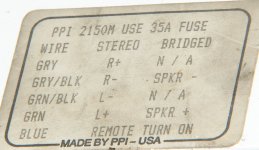
Yes, I'm sure. This is the M series, You are referring to the previous transistor series. This one has an inverting -180 degrees amp on the right channel and no external inverter is required, so you have to wire the 1st ( green) and the 3rd wire (gray/black). Infact these are connected to the transistor line. 2nd and 4th are common to ground.Are you sure about the common wires?
Early PPI's required an external inverter for bridging, and indeed used the two (+) leads for mono output. I don't recall the pin positions, but the two speaker negatives were common.
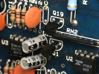
Ok, today I'll check it. Sorry, but in the first title I wrote PPI2150M. I confirm it's a 2050M. Thank you.I don't know where they are in the 2050. The muting transistors in the 2150 are shown below.
Ok, I found them, pulled out. Infact now amp makes bump on turning on and off. But.................. the problem still remains. 🙁
The noise is because the musing circuit is disabled.
If the problem remains and you're 100% sure the pot is OK, you will have to follow the signal through the amp to see where the level is becoming uneven.
If the problem remains and you're 100% sure the pot is OK, you will have to follow the signal through the amp to see where the level is becoming uneven.
The pot is ok on both sides, from 0 to 10kohm with logarithmic increase and decrease on the three pins. I tried to look where the signal goes but it's very difficult, too many paths goes here and there. Any other idea?
Without a diagram, I don't think there is a choice if you want to repair it. It's likely only a double-sided board so tracing shouldn't be that difficult.
It could be any component in the audio circuit.
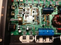
The white device is an opto-coupler and is likely used to drive the muting transistors that you removed.
The white device is an opto-coupler and is likely used to drive the muting transistors that you removed.
The white one is an optocoupler used by the muting circuit. The others are all dual op-amps with the output on pins 1 and 7. The left most is probably a gain stage after the pot. The second is probably the inverter for the right channel, so only one of the two op-amps is used. The third is probably part of the power amplifier circuit. Since the problem is only in the right channel, the middle op-amp is suspect.
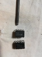
Ok, I pulled out the op amp C4558C from the 2050M. I have another PPI amp (2200M) for spare parts and I pulled out a 4558CP. Are they equivalent? You can see them in the shot, down the old one and up the "new" one. I tested them in diode scale and they are identical in values BUT on pin3 and 4 (where you see the hex key). On the suspect there is no conduction in any way, on the spare part there is conduction only in one way, open circuit in the other way. If you tell me they are equivalent, I proceed in soldering on the motherboard. Thank you.
Attachments
Last edited:
- Status
- Not open for further replies.
- Home
- General Interest
- Car Audio
- PPI Precision Power PPI2150M right channel sound low