Basics look fine: 10 ohm and 280 ohm check out. 20ohm between RCAs.
Now I think I done did it. I'm affraid to turn the amp back on now. I tried setting the bias at the same time on left and the right driver boards. I was monitoring the voltage on the right emitters with my dvm, and it want getting very high at all.
Then I heard a small pop, and a slight puff of smoke came out from under my transistor clamps near and around Q22 and Q23 output transistors. Of course I wasnt monitoring the voltage on that side. The output transistors got a little hot, but they dont look damaged outside. DVM set to diode shows everything as being A-OK, but when I apply power I hear the transformer buzzing a bit and I dont hold power to it for very long at all. Kinda scary.
Did I just blow this thing up?
Measure the resistance between the legs of the individual transistors. Do any read near 0 ohms in any combination (1-2, 1-3, 2-3)?
Sometimes, if the tab of a transistor contacts the heatsink, it will do the same thing (pop and a bit of smoke). Measure the resistance from the center leg to the heatsink to see if there is any continuity (at or near 0 ohms).
Do you have anything between the metal bar and the transistors?
Sometimes, if the tab of a transistor contacts the heatsink, it will do the same thing (pop and a bit of smoke). Measure the resistance from the center leg to the heatsink to see if there is any continuity (at or near 0 ohms).
Do you have anything between the metal bar and the transistors?
Looks like Q22 measures 1.2ohms and Q23 measures .7 ohms across pins 1 and 3. I think those TIP35Cs are out. I'm gonna carefully unsolder them and continue this venture. Setting these pots are more difficult than it seems. I measured and the one near the left chan driver board can actually hit 0 ohms. Thats what happened.
The metal bar is painted black, but judging by what I did above it was not the cause.
EDIT: I just took out Q23 and its shorted across 1&3. Q22 still on the PCB seems alright. The parts list grows, but I want to find the other bad parts before I order the lot.
What else can I try on the powersupply side?
Last edited:
No just paint. I also now realize that the TIP3x transistors are thicker and my bar is not firmly pressing everything to the heatsync. It was tight on the output transistors but not the smaller case ones. I'll fix that.
I've still got sound out of both channels.
I've still got sound out of both channels.
Last edited:
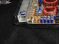
The simplest and best clamps I've found are like the one in the photo. The channel maintains good pressure along it's length and the silicone rubber ensures that pressure is applied to thinner components.
Did you remove one shorted output to allow you to continue testing?
Did you remove one shorted output to allow you to continue testing?
Attachments
Yes I de-soldered Q23 from the amp since pins 1&3 are shorted. Q22 still shows good on the scope and I can play tones out of both channels. it doesnt sound any better or worse.
Parts list thus far:
2x TIP35C (Q22 & Q23)
8x 0.68ohm 3w Emitter resistors
Parts list thus far:
2x TIP35C (Q22 & Q23)
8x 0.68ohm 3w Emitter resistors
Is the noise on the op-amp indicated in the previous image the same as the noise on the output (choppy, not constant)?
Yes its the same noise coming out of the speaker teminal. That noise must be in the upwards of 100K hz if I could take a guess. Of course thats inaudible but I hypothesize what may be happening is that noise is in a sort widening the audible frequencies.
So far I dont see the noise on the power fets. I start to see it around Q16, Q17, Q68 and Q69 on all pins, and also at the top of the largest capacitors on the board, and where the coil is soldered next to C27. Then I see it on almost every component afterwards.
So far I dont see the noise on the power fets. I start to see it around Q16, Q17, Q68 and Q69 on all pins, and also at the top of the largest capacitors on the board, and where the coil is soldered next to C27. Then I see it on almost every component afterwards.
Two terminals of the inductor will be extremely noisy.
On the video you posted, it showed a non-continuous oscillation on the output signal. You're correct that it's above audibility but the non-continuous nature of it is causing the problem. The frequency that it's switching on/off is what you hear.
Is the noise on the op-amp switching on and off like the noise in the video?
Im not so sure about anything anymore. To make that duel image/video from the other day I had to ground both probes; The probe across the speaker terminal I grounded to the other speaker terminal. The probe across the input RCAs had to be ground to RCA shield. If I removed the ground on the RCA, the noise seems to actually travel back to that probe.
Heres a picture of U3 and U7 LM837N opAmps. Both taken from pin 7. All the other opAmps match U7, and U3 produces the same signal on all corners.
U3 is the top line which is 3x fatter than the line coming out or U7 which is the bottom line. Both lines have traces of noise.

Heres a picture of U3 and U7 LM837N opAmps. Both taken from pin 7. All the other opAmps match U7, and U3 produces the same signal on all corners.
U3 is the top line which is 3x fatter than the line coming out or U7 which is the bottom line. Both lines have traces of noise.
Last edited:
I don't think that's important. U3 is early in the signal chain. The high frequency noise will be filtered out. You stated that the noise was not affected when the low pass crossover was engaged. The low pass filter would filter any noise from that IC.
What does the signal look like on the 2068 (pins 1 and 7)?
What does the signal look like on the 2068 (pins 1 and 7)?
2068 pins 1 & 7 have the same signal as the scope's bottom line. Clean like the other opAmps (except U3) but still displays the low noise like everything else.
Do you know a good place to source or substitute TI/Morooco TIP35C transistors? Are ST units good enough?

Do you know a good place to source or substitute TI/Morooco TIP35C transistors? Are ST units good enough?
The On-Semi components have been the most reliable from my experience. The brand in the photo was the absolute worst. The ST parts are OK.
TIP35CG ON Semiconductor Bipolar Power
TIP35CG ON Semiconductor Bipolar Power
Dang and that was an original component at the time from PPI. I guess they cut corners on a $600 amp. I'll go ahead and add all new TIP35C and TIP36C transistors to the list of replacement components. On-Semi brand.
Do you think these could be the whole problem? Where else can I pinpoint this noise on?
Edit: Does Mouser stock a good dual OpAmp that I substitute for the LM837N? I'd like to have these on hand for both the PC2150 and PC275.
Do you think these could be the whole problem? Where else can I pinpoint this noise on?
Edit: Does Mouser stock a good dual OpAmp that I substitute for the LM837N? I'd like to have these on hand for both the PC2150 and PC275.
Last edited:
I don't think the outputs were the problem.
Is the amp that you said sounded like a trumpet? If so have you been able to duplicate that problem after adjusting the bias?
I don't recommend that you use substitute op-amps. Using different brands of op-amps with identical part numbers can cause problems. Using op-amps that are significantly different is more likely to cause problems.
The 837 is a quad, not a dual.
Hey Perry,
Adjusting the bias will make the noise slightly go away at a cost of heating (and poping is seems) output transistors. The noise never perfectly corrected itself with the bias adjustment even out to 0.100v. I've since put it all back to 0.000v.
I guess opAmps are finicky things. If you say you dont see them as being a problem then I'll continue.
I'm going to do some output scoping on some low frequency signals with the HP filter on. If you say the LP filter would possible block anything noise related added by the opamps, then the oposite should be true with the crossover set to HP and a low frequency signal generated. I hypothesize I should see less of the audio frequency on the scope and hopefully more of the noise signal emitted. I'll run this through and hopefully get a better understanding where the noise is coming from.
I've put in place a 5am fast actng fuse because a 50 cent fuse is worth its weight with $3 transistors.
Any thoughts appriciated.
After over 100 posts in this thread I dont believe I've thanked you enough for your help. All I can say is I greatly appriciate it at any cost (Even when I pop a few components 🙂) Its my doing, and the cost of priceless advice.
My friend, thank you
If the outputs are properly clamped to the sink, higher biasing isn't a problem but 0.100v is extreme. For most amps, you don't need more than 0.005v.
I can't say that there is no defective op-amp.
Did you read the basic amp repair page (link in sig file)?
At this point, it's going to be able to do much more troubleshooting. When you had the intermittent oscillation on the output waveform there was something to look for. Does it still produce the buzzing noise? Or is there some other audible noise?
Perry,
Great news! I found the problem with the PC2150! I cant believe it myself, but I do indeed think its these opamps so please allow me to explain. First off I want to appologize for maybe not doing as you had said in the first few pages. This being a brand new endevor/experience for me I just didnt know 100% how to do everything asked of me.
To start, I wanted to go back to the basics. First, I found my tone generator had DC offset way out of wack. I corrected this by measuring DC accross its output and zeroing it out. Man I cant believe that was the first thing i should have checked when I got it home! Now its zero'd as best as I can at all frequencies and maximum amplitude.
Second, I desided to ook at offsets and bias on the amp like youve been having me do, and I noticed with no sound my scope would jump off-center when touching the speaker outs. i thought it was the scope, but nope! Again I measured DC across the speaker terminals and found IT to be off as well, so I carefully adjusted the pots in the middle of the board which I had previously never touched before. Now when the amp plays a 60hz note, DC volts reads zero at the terminals as it should. I'll likely have to re-adjust this after I get the new output transistors but for now I'll just leave it there.
3rd and finally, I got the trumpeting noise to finally STOP from the speakers. Setting the amp's crossover to low-pass was all I had to do; the noise was GONE and all I heard was clean, lucious bass. Its funny, because in my car I dont use this amp's crossover; I use the headunit's.
So, I think U3 opAmp is the problem with this amp at full range. If you agree or have any more tests I should do please let me know! Im so excited!
I'll likely just go ahead and order about 10 quad opAmps for this and the PC275.
I'm so happy!! My wife is happy!! My dog is happy!!
- Status
- Not open for further replies.
- Home
- General Interest
- Car Audio
- PPI Powerclas PC2150 and PC275 need repair ideas