hello
the rookie is trying to fix nice PPI Pc2600.2 I'm seeing few issues
1 -green light comes on but the amp is not powering .all fets are tested and no shorts and no repairs in the past that i can see.At the power supply fets I'm getting 1v on the gates and 11 on the middle legs
2- one of the driver cars looks like it was getting hot -bit brownish under it
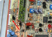
3 the mystery- one resistor is mounted on the board but not soldered r192 its between q71 and q72 transistors .it looks like it has never been soldered to the board just mounted
the rookie is trying to fix nice PPI Pc2600.2 I'm seeing few issues
1 -green light comes on but the amp is not powering .all fets are tested and no shorts and no repairs in the past that i can see.At the power supply fets I'm getting 1v on the gates and 11 on the middle legs
2- one of the driver cars looks like it was getting hot -bit brownish under it
3 the mystery- one resistor is mounted on the board but not soldered r192 its between q71 and q72 transistors .it looks like it has never been soldered to the board just mounted
1. That would generally mean that the power supply is running.
2. Does it look like the board it discolored or could it be something on the board? Is it discolored top and bottom?
3. Is there any solder on the bottom of the board? It seems like it would have fallen out if not soldered in.
4. Operating the amp without the bottom cover in place is dangerous because the transistors can overheat and fail quickly, especially if there is a problem. When troubleshooting it without the cover, install shunts on the 2-pin headers JP1 and JP4 while troubleshooting when the cover is not tightly screwed down. There are regulator transistors on each side of the amp. They will get hot and can fail even if there are no problems with the amp. Watch their temperature closely. If you do it by touch, only touch the plastic part of the transistor.
there is discoloration on both top and bottom of the board under the driver card .light brown discoloration .soldering looks bad like cold solder will do them again
that r192 can be soldered on the top of the board only ,i dosent look like it has ever been soldered there but why the hell should someone put it there ???resistor legs are gently folded so its stays on the board but not soldered
that r192 can be soldered on the top of the board only ,i dosent look like it has ever been soldered there but why the hell should someone put it there ???resistor legs are gently folded so its stays on the board but not soldered
Since the legs are folded/bent, I'd suspect that someone was working on the amp, installed it and forgot to solder it. If the legs are bent, it could have been making good enough contact to allow the amp to work, or maybe they gave up on trying to repair it.
I would expect the rail voltage to be a bit higher. What is the 12v supply voltage at the amp's power/ground terminals?
i was feeding the amp thru adjustable power supply -11 v at the time of the first test ,readjusted to 12v and the rail voltage went to 40 ,is this the correct .the other driver card have some discoloration under as well .still no audio
so I'm back to this boy,i did some testing on
op in the power supply lm 393n
pin 1: 0.1v
pin 2: 3.5v
pin 3: 2.4v
pin 4: 0
pin 5: 0
pin 6: 0
pin 7: 0
pin 8: 4.5 v
pin 6 and 7 are connected in the board
U1 SG3525A Pulse width modulator
Pin 1 Inverted Input = 2.5V
Pin 2 Non-Inverted Input = 2.5V
Pin 3 Sync = 0.00V
Pin 4 Osc Output = 0.1V
Pin 5 Ct = 0,0V
Pin 6 Rt = 3.5V
Pin 7 Discharge = 2.0V
Pin 8 Soft Start = 4.5
Pin 9 Compensation = 1.0V
Pin 10 Shutdown = 0.00V
Pin 11 Output A = 0.9 = drives the MOSFETS at the Gate
Pin 12 GND = 0.0V
Pin 13 Vcc = 14.0V
Pin 14 Output B = 0.9V = drives the MOSFETS at the Gate
Pin 15 Vcin = 12.0V
Pin 16 Vref = 5.10V
so looking thru few other listings here for amps using the same modulator people are getting 3-4 volts on legs 11 and 14
any ideas
yes it is I'm getting -+ 40 volts on the outputs
maybe I'm going blind but i do not see any thermo resistor on the board at all
maybe I'm going blind but i do not see any thermo resistor on the board at all
Last edited:
ok i saw them .should't the red photo diode light up when the amps is on ,mine dosent
do u think the problem could be in the driver cards
do u think the problem could be in the driver cards
I don't know if the LED in the middle of the board should be lit. I don't remember seeing one lit.
Do you have positive and negative supply voltage (approximately ±15v) on the power supply pins of the op-amps in the preamp section of the amp?
Do you have positive and negative supply voltage (approximately ±15v) on the power supply pins of the op-amps in the preamp section of the amp?
Does the amp make any sounds (including pops and clicks) when you operate all of the controls through their entire range?
If it's not producing audio, are you sure that the signal source is working properly?
If you plug the RCAs in after the amp is on, does the amp make any noise?
If it's not producing audio, are you sure that the signal source is working properly?
If you plug the RCAs in after the amp is on, does the amp make any noise?
- Status
- Not open for further replies.
- Home
- General Interest
- Car Audio
- PPI PC2600.2 power supply issues help needed