I bought a Precision Power A404 Art series Amp with the advance knowledge that the 'rear' audio channels were not functioning. Thus far, I've only taken photos, cleaned up old silicon, and taken tentative steps to remove the board from the chassis.
My background in electronics is limited and stems almost entirely from my time as a radio maintenance technician for the Air Force between 2004 and 2008. Most of my work involved following instructions and most of my troubleshooting involved seeing a broken part, smelling a burned part, sensing an extra hot part, or feeling a loose part. Component level troubleshooting was rare and detailed schematics and nominal signal descriptions were provided for practically every signal. Given that I have neither schematics nor a working copy to test against, this repair may be beyond reasonable for me at this time.
My first goal is to understand the amplifier to the point of being able to identify major components of the power supply, signal processing, and output circuits. Secondly, I want repair the amp and return it to service.
The amp bottom cover has a repair sticker from '96 and another from '98. I don't know when this amp was manufactured. The case reads A404 and the board is marked as REV D.
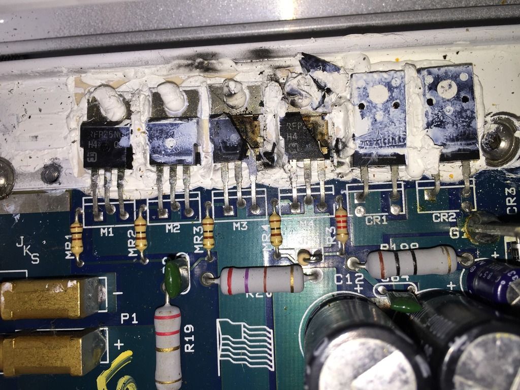
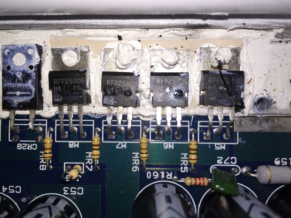
Overview of the board with visual damage noted. The ground bar is not secure at one end and three of either power supply FETs have burned. The main power fuse is not present. Capacitors show no obvious damage, nor do resistors or any other components. Given the obvious power supply damage and missing fuse, presumably blown, I have elected not to power the system up until power supply components have been tested and failed components replaced.

My first task is to remove the board from the case. There is a fair amount of silicone? adhesive under the large inductors that seems to be gluing the board to the case. I could be wrong, which is why I'm taking my time.
My background in electronics is limited and stems almost entirely from my time as a radio maintenance technician for the Air Force between 2004 and 2008. Most of my work involved following instructions and most of my troubleshooting involved seeing a broken part, smelling a burned part, sensing an extra hot part, or feeling a loose part. Component level troubleshooting was rare and detailed schematics and nominal signal descriptions were provided for practically every signal. Given that I have neither schematics nor a working copy to test against, this repair may be beyond reasonable for me at this time.
My first goal is to understand the amplifier to the point of being able to identify major components of the power supply, signal processing, and output circuits. Secondly, I want repair the amp and return it to service.
The amp bottom cover has a repair sticker from '96 and another from '98. I don't know when this amp was manufactured. The case reads A404 and the board is marked as REV D.
Overview of the board with visual damage noted. The ground bar is not secure at one end and three of either power supply FETs have burned. The main power fuse is not present. Capacitors show no obvious damage, nor do resistors or any other components. Given the obvious power supply damage and missing fuse, presumably blown, I have elected not to power the system up until power supply components have been tested and failed components replaced.


My first task is to remove the board from the case. There is a fair amount of silicone? adhesive under the large inductors that seems to be gluing the board to the case. I could be wrong, which is why I'm taking my time.
You need to replace all 8 of the power supply FETs.
Confirm that all of the gate resistors are within tolerance.
If there are driver transistors between the driver IC and the FETs, check them as well.
It could have shorted output transistors so you need to check those.
Be aware that you cannot operate the amp at anything more than idle without the bottom cover tightened down. Even at idle, you have to monitor the temperature of the transistors.
You need to replace all 8 of the power supply FETs.
Confirm that all of the gate resistors are within tolerance.
If there are driver transistors between the driver IC and the FETs, check them as well.
It could have shorted output transistors so you need to check those.
Be aware that you cannot operate the amp at anything more than idle without the bottom cover tightened down. Even at idle, you have to monitor the temperature of the transistors.
I have a lot to learn.
I understand replacing all 8 Power Supply FETs and checking gate resistors.
I'm not clear on driver transistors, IC, and FETs. I will try to learn the functions of the five ICs on the board. One has 16 pins, one has 6 pins, and three have 8 pins.
The three 8 pin modules have been described as OPAMPs, which I presume are tied into the nearby POTs and control output. How they do that... to be determined. I would expect the purpose of the 16 pin IC to be modulation of the of the input signal with the power supply output before it passes through the driver transistors.
The six pin IC... no idea.
I'll look for a suitable aluminum channel to cut and use as a clamp for testing. I saw a photo of that setup in someone else's thread. It's going to be a while before I get that far though.
Thanks for the help. I downloaded your repair guide after I read the online portion.
Next up is more learning. After that, component testing.
This won't be a quick project.
Download the datasheets for the various ICs. That will tell you what they are.
The 8-pin ICs are likely all op-amps. The 6-pin IC is likely an opto-coupler. The 16 pin IC is the power supply driver IC.
Do yourself a favor and read through the tutorial from top to bottom in the directory following all links on all pages and reading the linked pages in their entirety. Don't do like some people and just scan it quickly. If you read through it as suggested, it will be well worth the cost.
Also, be sure to make backup copies of the files as suggested on the page you downloaded it from.
- Status
- Not open for further replies.