As you have realized you need a current sink that draws the same current as the output tube. It will be exposed to an AC voltage equal in magnitude (but opposite phase) to the output tubes plate voltage. It must hold a constant current over this voltage range. It must also present a high impedance to that AC voltage. This is pretty much the deffinition of a CCS. A simple CCS made with solid state or tube circuitry will work, although solid state becomes unreliable at the kilovolt and above voltage levels. Like you said, this becomes a push pull amp, without grid drive to one tube. I have even seen a circuit for such an amp that used a switch to turn the grid drive on or off. It used 211's.
There have been numerous discussions over the years as to what causes the "single ended sound". One of the long standing beliefs is that the DC current flowing through the transformer moves the operating point of the transformer into a more linear region of its BH (magnetic performance) curve. It also helps eliminate the hysteresis effect. I have experimented with push pull transformers in SE amps, and I believe that there is some truth to those statements. I have used UTC LS-57's, some Fisher, Dynaco, and other quality P-P transformers, with an IXYS 10M45 CCS chip on the unused side of the secondary. I find that there is a loss of detail in the sound when doing this, although the bass response is better than an average SE transformer.
These were not scientiffic tests, and my hearing is not so good any more, but you might want to perform your own tests before building an amp. I will purchase some true SE transformers for my big (833A) SE amp some time in the next few months.
In the mean time I (and others) are experimenting with chokeless parafeed (CCS in place of the choke) and H bridge technology to eliminate the cap. So far this looks good, but the efficiency is bad, very bad, and the voltage requirements are nearly double that of a conventional SE amp. This will likely limit its use to conventionally sized SE amps, but I will try anything once, and I have plenty of 833A's and big power transformers.
I don't see me spending $1200 on iron, But I might try to find a supplier who will sell me a few hundred pounds of EI laminations and try to make a pair. Cant be that hard. Make a mandrel and spin some wire into it and slap some iron in the hole, right?
Or I may ditch the idea and persure the 6C33C OTL Cirlotron, or maybe SE plate loaded with split supply and servo control the grid bias to null offset and avoid the dreaded output cap....or maybe, an 833 PP somewhere around 400-600W
I've already shelved the 833 project once due to not having any of the high voltage measurement equipment or parts lying around. I will need to do some child proofing fo my 7 year old before I can put juice near anything. My wife and daughter use my computer in my lab/workroom when I'm not around, and I sometimes can tell thing have been kerfingerpokended, even thogh I've been quite clear about not messing about in my stuff. Until now, everything's been under 160V.
If your buying new cores rather than using scrap laminations you might look at other core designs than EI, such as double C cores.
Nippon Core and others offer tape wound cores as fine as .1mm. These are mostly intended for 400hz transformers, bu the'll work in audio just fine. Gapped cores are available.
Nippon Core and others offer tape wound cores as fine as .1mm. These are mostly intended for 400hz transformers, bu the'll work in audio just fine. Gapped cores are available.
My wife and daughter use my computer in my lab/workroom when I'm not around, and I sometimes can tell thing have been kerfingerpokended
Seriously, don't even think about playing with the voltage levels needed in an 833A amp until you have a secure work environment. You don't get a second chance with 1500 volts.
The "clip leads with 1500 volts" experiment on my web page was performed in my lab/workroom. My wife doesn't go in there with out me present, she is "afraid of that stuff". This is good. I have everything on a master switch so the lab is "cold" when I am not present. Actually all of the HV stuff are on two series connected kill switches so it is hard to accidentally power it up. Make sure everyone in your house knows how to kill the power in an emergency.
I got my wife and daughter their own computer so they didn't need to use mine. When your kids get old enough to download stuff and IM their friends, you don't want them on your computer anyway.
The power transformers and most of the parts for my 833A amp were acquired off of Ebay. Some of them came from members of this forum. Find some large resistors, 50K 20 watt, or so and make a voltage divider. The values are not critical, just get a few that are the same. I use 4 in series, that way I can measure up to 2400 volts with a $5 digital meter.
Here's the big question.
How cheap can you get off on a SE transformer that can stand 400ma and 1500 ohm impeadance and run over 100W? Is it totally insane to think you could wind your own with 29 ga M6 laminations and a wooden former mandrel chucked up in a drill with a turn counter.
I've seen a few websites with the formulas and design guidelines, and I think I could way overbuild it cheaply and play with the gap size to optimize the saturation/inductance trade offs.
I'f I need to get the pipe outta my mouth, let me know. Or egg me on and I'll report my findings. I guess I could DC couple a big amp and hook it up to test my results. The inductance drops when the coil starts to saturate; I guess I could check the impeadance of the primary, then bias the seconary with DC, untill I see a drop in impeadance, calculate the turnsxamps and back into the saturation, then only bias to 1/2 that value.
It can't be such a black art. It's a simple thing. A few turns of wire, a core, no biggy.
I realize I'll need to secure the area a little better befor I power up a 1500V monstrosity like the 833. Another reason to chase the OTL 6C33C.
Well, Im contemplating cutting the core of a 300ma ~70,000VCT x ray transformer and just trying it as is (was thinking about it as a choke anyhow). Lo Fi, perhaps, (no M6 here), but it was cheap, so why not?
Tweeker,
I used a 150 kV (75-0-75) X-ray xfmer with audio power on the 220 volt primary to power a homemade electrostatic speaker panel as an experiment. The transformer was not modified at all. I also used a HVDC bias supply in series with the speaker panel. As I recall the higher frequencies were not there. IMO the turns ratio is too big for use an a tube output xfmer, but that might change in a HV application of 3-5 kVDC using an 833A or 450TL/TH, etc. I haven't looked at this at all.
Your 20 kVA xfmer will be a heavy brute! You ought to have lots of L however!
I don't have any (successful) transformer winding experience, so I had an experienced transformer winder try to make me one. I had previously purchased a pair of 300B transformers from him on Ebay. I liked them so much that I bought 20 more. He agreed to try to make me a 100 watt SE transformer for a reasonable fee. I specified a 5K ohm 300 mA transformer rated to 3KV. I got the first transformer and tested it. The bass was amazing, It sounded great. I could get over 200 watts from the test amp. When I ran frequency response plots there was an obvious rolloff beginning at 10KHz. I tried this transformer in an existing 300B amp, and the problem was in the transformer. The transformer guy tried to make another transformer with similar results. Other "experts" have told me that an SE transformer above 50 watts would be difficult due to winding capacitance and leakage inductance. If you do decide to "roll your own" you might want to try a smaller one first.
Do you have an operating point in mind to get to a 1500 ohm load? I was running 1500 volts on the plate, and tried currents from 150 to 300 mA. My transformer was wound to 5000 ohms and this proved to be perfect for these conditions.
The Hammond 1642SE is rated for 75 watts 5000 ohms. It is available for $239 at Angela or at Radio Daze. I have asked before if anyone out there has tried them, but got no response. I will probably go this route when I have the time and bench space to build the stereo amp. I am going to use the above transformer to build a guitar amp using an 833A.
Frequency response plot of the prototype 833A amp using the above transformer is on my web site. It shows some reactive effects in the high frequency ranges.
http://www.tubelab.com/833SE.htm
I have a friend who runs EIMAC 250s in his trasmitter. Wishes the EIMAC tubes werent so damn pretty due to collectors.
It seems like the 250TL/TH might be a good choice to push the Hammond to its wideband limits.
It seems like the 250TL/TH might be a good choice to push the Hammond to its wideband limits.
I have about four each of both 833A and 450TL in stock. Yup, those 450TH sure look purty! Drive requirement on them isn't bad either. The idea of a big amp, perhaps P-P has been in my mind for a long time, ever since I made a P-P-P amp from four 814's back around 1975 and easily got 400 watts RMS from two Hammond 50 watt o/p xfmers. one on each pair of bottles, secondaries in parallel to the load, with 1400 volts on the plates. The 814 is a DH tetrode that has a plate cap and looks like a KT88 but 2-1/2x as tall. Nice looking power tube for home audio and the filament is bright like an 845, 805, 810. I had four dozen Westinghouse NIB and I kick myself all the time for leaving them behind in a major move years ago.
To fulfill such dreams one needs much voltage, time and iron.
To fulfill such dreams one needs much voltage, time and iron.
I was just going from memory, and it's been a few months since I did the thinking. If you say the optimunum load is 5K, that's a believable slip to 1.5K
Here's an idea, buy 2 of the 75W Hammonds and run them parallel. Each secondary seeing 1/2 of the load should undo the 1/2ing of primary impeadance by paralleling. If it doesn't work parallel, don't buy the second set, but build a pair of amps to use 1 per monoblock(since there's no way to lift a stereo built with these and the needed power transfomer and chokes)
If you've seen my Alephs, you'll know I have no problem burning a few KW's. Maybe I'll biamp with the Alephs on the woofers, and 833 for the midbass and tweeters. Should be quite dynamic.
CORRECTION TO MY PREVIOUS POST 
I stated that the 814 was a tetrode. OOPS! It has 3 grids. That's a pentode. It was kinda late.
I stated that the 814 was a tetrode. OOPS! It has 3 grids. That's a pentode. It was kinda late.
If you take care with insulation ratings (dont forget the filament transformers etc.), you might also try series with higher voltage and lower current.
Silicon stuff in the circuit might be a sticking point with this though.
Well, if biampings in, you could go SE GM70s on mids and tweeters with SE 833A on woofers. HF rolloff in the output transformer wouldnt be an issue then.
Silicon stuff in the circuit might be a sticking point with this though.
Well, if biampings in, you could go SE GM70s on mids and tweeters with SE 833A on woofers. HF rolloff in the output transformer wouldnt be an issue then.
Tweeker said:Well, the 814 is a beam tube. Easy mixup.
well yes, It worked so very well in my 400 watt RMS breadboarded guitar 'booster' amp that it really made me beam. 😀
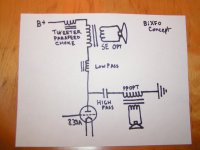
Bitransformer concept for large SE tube amplifiers.
An externally hosted image should be here but it was not working when we last tested it.
Attachments
Tweeker,
The biggest problem with that circuit that I see immediatly is that the LPF choke and the other also in series with the bass OP xfmer will soak up some of the available bass signal, just as voltage and power divides among strings of resistors in series. You are not going to get very good efficiency in LF energy transfer to the LF speaker.
Placing an iron choke in series with an output xfmer that is too small (not enough L) to operate at the lowest audio frequencies is a trick that can be employed to get 20 Hz out of a smallish xfemer that otherwise saturates, but it is at the expense of output power and circuit efficiency. No free lunch. That seems to be the law.
Well, the LP choke could be removed, and if need be placed on the secondary side.
A 2 course lunch of biamped GM70s might be more sensible, but sometimes I like to have a large dessert instead of a sensible meal.
A 2 course lunch of biamped GM70s might be more sensible, but sometimes I like to have a large dessert instead of a sensible meal.
Tweeker said:Well, the LP choke could be removed, and if need be placed on the secondary side.
I think that would work.
A 2 course lunch of biamped GM70s might be more sensible, but sometimes I like to have a large dessert instead of a sensible meal. [/B]
I think your idea has merit in that it provides an opportunity to use a PP OPT to obtain two band split outputs from a SE output stage as an alternate to building an entire extra output stage with a second tube and it saves having to buy a more expensive (than P-P) second SE output xfmer..
This would be a simple modification of existing SE amps that have enough muscle and room for the extra xfmer and coupling cap needed.
Driver level balancing will needed to be accomplished by passive pads in front of the loudspeaker drivers.
OK, in another thread I was informed that Angela has the big Hammond transformers on sale for $222 USD each. I decided to go for it. I have been calling Angela every hour for two days, same result, no answer. I will keep trying. I will start construction on "the big one" when I have the transformers in my posession. I have all of the other parts.
833A SE using 45's as drivers through PowerDrive. The prototype put out over 200 watts on 1500 volts. I have enough power transformer for 2000 volts. I will prototype the entire amplifier (both channels) before final construction. Details will be on my web site as they happen.
833A SE using 45's as drivers through PowerDrive. The prototype put out over 200 watts on 1500 volts. I have enough power transformer for 2000 volts. I will prototype the entire amplifier (both channels) before final construction. Details will be on my web site as they happen.
- Status
- Not open for further replies.
- Home
- Amplifiers
- Tubes / Valves
- PP transformer for SE use