I've read several comments about PP toroidal transformers needing balanced DC current. I know that this can be mitigated with garter bias, but what if I want to use fixed bias?
I'm curious what the threshold is, and what happens. Is a 1mA imbalance okay? 5mA? Does it cause increased distortion? Or damage to the windings?
I'm curious what the threshold is, and what happens. Is a 1mA imbalance okay? 5mA? Does it cause increased distortion? Or damage to the windings?
No damage, possible distortion of LF. It really depends on the coil. I've had a 120mA (missing tube) mismatch on mine with no noticeable distortion, but I use power transformers interleaved to have my OPTs. They are designed for much more primary current than a tube OPT.
Consider an AB-4 or AB-Q automatic bias module from Pavel audioamp.eu. I won't build a fixed biased amp without one anymore.
The AB-4 uses JFET opamps, so be careful when you solder it if you get that one. If you ask Pavel, he can make the AB-4 using socketed DIP-8 instead of SMD.
Consider an AB-4 or AB-Q automatic bias module from Pavel audioamp.eu. I won't build a fixed biased amp without one anymore.
The AB-4 uses JFET opamps, so be careful when you solder it if you get that one. If you ask Pavel, he can make the AB-4 using socketed DIP-8 instead of SMD.
If you see the magnetization characteristic
http://web.mit.edu/6.013_book/www/chapter9/ch9-946.gif (http://web.mit.edu/6.013_book/www/chapter9/9.4.html)
the PP transformer steady state is at the null point - origo - (B=0, H=0).
Any constant magnetization (current imbalance) shifts this origo -for example- to the positive region, so the exploitable flux (B) and the maximum power decreasing.
Because the null point shifted, the symmetry of B-H curve is become distorted, its results higher distortion at large swing (at lower frequencies).
The current imbalance doesn't ruin it the transformer, but the operation deteriorates.
Toroidals saturate very quickly with DC current in them, more so than EI core types. Keep steady DC out.
That's why my pair of 250VA coils interleaved don't mind 120mA misbalance when the SE power is probably about 1W 😀 Normal OPTs aren't 250VA @25Hz, and don't have a primary DCR of 12R, either.
FWIW I now only have one pair of EI OPTs and they are for sale along with the amp they are in.
FWIW I now only have one pair of EI OPTs and they are for sale along with the amp they are in.
Last edited:
Its absolutely critical that DC balance is maintained unless the transformer has a distributed gap built into the toroidal core. Most will not have a distributed gap. Even a few mA of unbalance can have a profound impact on low frequencies.
Garter bias works amazingly well at maintaining bias. Also bypassed matched CCS's are very good at maintaining balance. Garter bias is wasteful of power compared to CCS and this become much more critical on low mu output tubes.
Maximum inductance, and hence maximum low freq response, is achieved with the smallest VA rating of your transformer, I would size at 4x the expected Watts output. The smaller the transformer the greater the impact of imbalance.
Shoog
Last edited:
There are no general recommendations as to allowable DC imbalance current. It depends on transformer. It can be measured. Measure primary inductance first with no DC, then after injecting increasing DC currents into secondary from a current source. Knowing transformer ratio, calculate equivalent primary DC current; magnetization is proportional to ampere-turns. 10-20% drop in primary inductance is acceptable.
I made a subwoofer transformer using 3 kVA toroid core. Half-primary is 56 H with no DC, dropping to 50 H with 4.5 mA unbalanced DC. I have to use balance indicator and trimpot balance adjustment (60 mA current per side).
I made a subwoofer transformer using 3 kVA toroid core. Half-primary is 56 H with no DC, dropping to 50 H with 4.5 mA unbalanced DC. I have to use balance indicator and trimpot balance adjustment (60 mA current per side).
Realistically, close enough is good enough. Even with pots and a traditional bias adjustment, a couple mA won't do much. If you care that much, use a bias module or bypassed CCS cathodes? Just built it
sser2: Did you try two coils wired like in the pic? With only one coil, I get 14.7W@30Hz. with two wired like this, I get full power 115W.
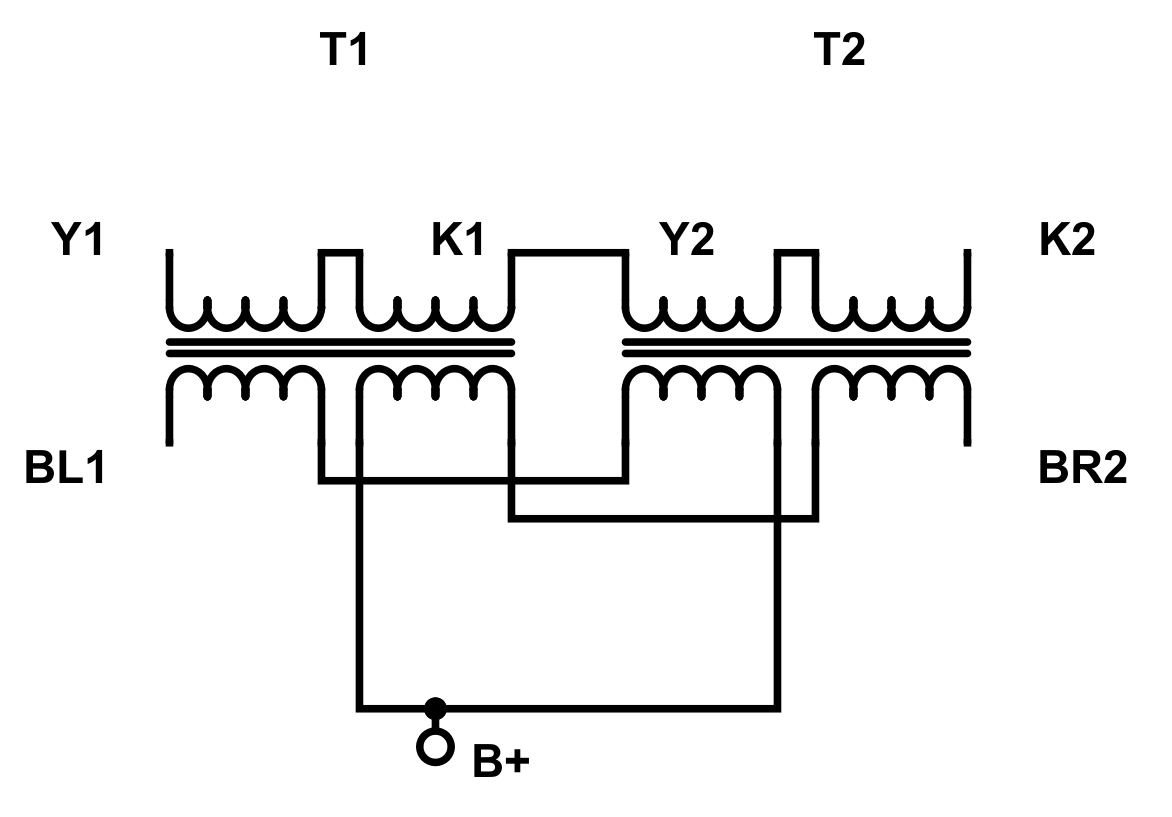
(PPP triode 6P45S, 120mA idle per tube, 1k Ra-a)
sser2: Did you try two coils wired like in the pic? With only one coil, I get 14.7W@30Hz. with two wired like this, I get full power 115W.
(PPP triode 6P45S, 120mA idle per tube, 1k Ra-a)
Last edited:
Is it a combination of 2 transformers? Never thought about it. With one core, inductance is square of turns, but magnetization is linear, so I thought single core is more advantageous.
I use parallel super-6BG6GA with 800 V plate and 30 mA per tube.
I use parallel super-6BG6GA with 800 V plate and 30 mA per tube.
It's two transformers. Twice the turns, twice the core. 230V@25Hz or 460V @ 50Hz - take your pick 🙂 With my triodes having B+ 320, and the lowest Va-k of about <40V, this set up makes all the bass you need.
Point being, you could have probably used two 250VA coils for the same result with less cost and size/weight by interleaving them.
Point being, you could have probably used two 250VA coils for the same result with less cost and size/weight by interleaving them.
Last edited:
Is it true that if you saturate a transformer with a low frequency note,
That the low frequency note will inter-modulate with the mid frequencies?
At saturation, the transformer is no longer linear, Right?
Doesn't that non-linearity apply to at least mid frequencies, during the time when the peak is in saturation?
Opinions, please.
Thanks!
That the low frequency note will inter-modulate with the mid frequencies?
At saturation, the transformer is no longer linear, Right?
Doesn't that non-linearity apply to at least mid frequencies, during the time when the peak is in saturation?
Opinions, please.
Thanks!
When the current is hitting sat on a 30Hz sine, the HF component is squashed, too. If the HF is fine, I don't think it's coil sat.
Crank this song in places (~3:00) and see if the HF modulates with the LF. Yearning (2017 Remastered) - YouTube If it does, maybe you're running out of tube current but not saturating the coil...
Crank this song in places (~3:00) and see if the HF modulates with the LF. Yearning (2017 Remastered) - YouTube If it does, maybe you're running out of tube current but not saturating the coil...
Last edited:
The Heathkit 5M assembly manual provides a plot of distortion increase with dc bias imbalance:
http://www.mcmlv.org/Archive/HiFi/HeathkitW5M.pdf
I tested a vintage hi-fi transformer for PP primary inductance roll-off with dc current imbalance: last section of this link https://www.dalmura.com.au/static/Choke%20measurement.pdf
http://www.mcmlv.org/Archive/HiFi/HeathkitW5M.pdf
I tested a vintage hi-fi transformer for PP primary inductance roll-off with dc current imbalance: last section of this link https://www.dalmura.com.au/static/Choke%20measurement.pdf
The point was that it doesn't take much at all for a gappy EI transformer to show a performance change - and the characteristics of distortion and inductance for a toroid will show far less tolerance to imbalance, so failing anyone doing some tests on a toroid, those tests on an EI are indicative of what will happen.
Fair point. What if the transformer is designed for amperes instead of milliamperes? Then how does the DC offset work out? Isn't it proportional? And no gap.
trobbins,
Thanks for posting both of those!
More than once on the Valves / Tubes threads, I have posted that the very last page of the Heathkit W5 manual has a chart of the distortion versus un-balanced primary current (it is a hidden nugget, unknown to many people).
The real nugget:
The distortion is that bad when the currents are un-balanced, even with its global negative feedback. Negative feedback can not fix that problem.
Only balancing the current can fix that problem.
By moving the Heathkit W5 amplifier, and the W5 manual to below the equator, it becomes an M5 amplifier.
Hey look! It's Single Ended! LOL
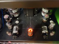
As expected, I get about 1W (instead of 30W+) output with an 60mA mismatch the f*cking tube is out of the socket FFS!), but it's not la fin du monde. It makes me wonder if the output would be better but still SE if instead of removing the tube from it's socket, I removed it's drive and grounded it's grid instead. No more mismatch but still single ended. 🙂 Wire it to a switch and call it a feature!
As expected, I get about 1W (instead of 30W+) output with an 60mA mismatch the f*cking tube is out of the socket FFS!), but it's not la fin du monde. It makes me wonder if the output would be better but still SE if instead of removing the tube from it's socket, I removed it's drive and grounded it's grid instead. No more mismatch but still single ended. 🙂 Wire it to a switch and call it a feature!
Attachments
Last edited:
Perhaps a test is to measure distortion profile with a normal, well balanced PP amp that uses a toroid OPT, then include some form of constant current load on one side, and remeasure the distortion. There may well be second order effects coming in from the load, but I guess if the voltage swing across the toroid primary halves is small compared to B+ then the current through even a loading resistor will be constant to a first order, although it is large order voltage swings that are likely the issue here.
Ideally if I understand it right, You'd want a CCS on one side with a really high Z instead of a resistor? Otherwise won't one side of the transformer follow the other if it has a low Z path? Someone told me a triode makes a crappy CCS. Everything the makes a triode great is lost on providing a high impedance save for cascode.
Still. Short one grid to ground and single ended it is. Just not as elegant. I Short pin 1 and 3 of an XLR to the same end.
Still. Short one grid to ground and single ended it is. Just not as elegant. I Short pin 1 and 3 of an XLR to the same end.
- Home
- Amplifiers
- Tubes / Valves
- PP toroidal OPT - how critical is DC balance?