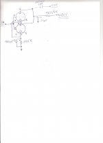
Please need help, how can do to convert this PP schematic in parallel?
An externally hosted image should be here but it was not working when we last tested it.
Please be a little more specific about what you want?
What do you want to achieve?
What is the purpose?
What do you want to achieve?
What is the purpose?
Hi!
What exactly do you want to achieve? The circuit you've shown is not PP and what do you mean by 'parallel' ?
Thomas
What exactly do you want to achieve? The circuit you've shown is not PP and what do you mean by 'parallel' ?
Thomas
I am sure merlin PP refers to that this circuit is called "Shunt Regulated Push Pull". To parallell the two triode-halves to get a conventional CC-stage is no big deal.
@ markusA & Vinylsavor
I want to convert the push pull in two triode-halves paralleled with the same valve.
@revintage
Isn't any advantatge to convert the push pull in parallel triode? could you elaborate?
I want to convert the push pull in two triode-halves paralleled with the same valve.
@revintage
Isn't any advantatge to convert the push pull in parallel triode? could you elaborate?
Hi,
Try this:
connect both systems in parallel, use half the cathode resistor value which is in now and double the cathode bypass cap. Connect the output coupling cap to the anodes and a plate resistor 5k/10W from anodes to B+.
Alternatively you can try just single systems: Disconnect the upper system in the SRPP stack, or better ground all unused elements. Leave the cathode R and C and use a 10k plate load resistor.
Best regards
Thomas
Try if you like SE by moving the output cap to below the upper 330ohm. This way the lower triode will be loaded by, in the ballpark of, 20k. This if we assume Ri being just below 10k at this low Ia.
About parallelled 6922 halves I have no idea if it sounds good, haven´t tried. But you have the answer about how to do in Thomas post above. (Our posts crossed)
About parallelled 6922 halves I have no idea if it sounds good, haven´t tried. But you have the answer about how to do in Thomas post above. (Our posts crossed)
Last edited:
Hi,
I forgot to add: you should then also change the bias voltage of the heater. As a first try you can simply reference the heater to ground. Or change the voltage divider which elevates the heater to values which will bring it ti about +25V.
Thomas
I forgot to add: you should then also change the bias voltage of the heater. As a first try you can simply reference the heater to ground. Or change the voltage divider which elevates the heater to values which will bring it ti about +25V.
Thomas
I couldn't make out the B+ voltage in the schematic, it is difficult to read. For my suggested mod it should be 180...
Thomas
Thomas
Sorry I forgot to told you that the heater now isn't shunt type, each tube has is own heater. Voltage B+ before 4k7 is 180V. Could you draw & post an schematic with changes & values to do?
Hi!
No that will not work. The 22uF would short out the output signal.
Maybe you should read up some basics before you attempt such mods.
As has been suggested on this board, Morgan Jones books are brilliant.
Best regards
Thomas
No that will not work. The 22uF would short out the output signal.
Maybe you should read up some basics before you attempt such mods.
As has been suggested on this board, Morgan Jones books are brilliant.
Best regards
Thomas
- Status
- Not open for further replies.
- Home
- Amplifiers
- Tubes / Valves
- PP to parallel