Hello All,
I inherited some large EI type output transformers that were used in an SE 845 amp. I've examined and measured one of the OPTs and find that it is actually a PP output transformer. Brand is Northlake Engineering Inc. Stamp marks on the side of the transformer are A139-103, 454216, 17227297.
The transformer has three leads on the primary and 4 leads on the secondary. Primary: Blue, Red, Blue/White; Secondary: Black, Yellow, Orange, Purple.
DCR on primary measures as:
Red - Blue: 68Ω DCR
Red - Blue/White: 70Ω DCR
DCR on secondary measures as:
Black - Yellow: 1Ω DCR
Black - Orange: 0.8Ω DCR
Black - Purple: 0.5Ω DCR
Impedance measures as:
54.1V AC (60 Hz) applied between Blue and Blue/White leads produces the following voltages on the secondary:
Black-Yellow: 3.34V AC
Black-Orange: 2.23V AC
Black-Purple: 1.68V AC
Also, the AC voltage measured between Red and blue primary leads (when AC input is hooked between blue and blue/white leads) is 27.05V, confirming that the red lead is tapped half way on the primary.
The secondary voltages are approximately a factor of root(2) apart, so I assume:
Yellow = 16Ω
Orange = 8Ω
Purple = 4Ω
This implies a primary impedance of approximately 4.2KΩ.
These look and act like big PP output transformers, that guess is supported by the red primary lead being mid position on the primary, and the fact that it's red in color, where the end leads are blue and blue/white.
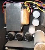
The lamination stack is huge on these: 2" width, 4.5" height, 3.75" depth. They look like they could support 80 to 100 Watts of PP power. Size-wise they are at least as big, perhaps slightly bigger, than Dynaco Mk III (A431) output iron, if that helps for the visual on how big they are.
I don't know if this will work, but if I load the 4 ohm tap (purple) with an 8 ohm speaker, it'll reflect approximately 8.4KΩ to the primary. Load line analysis of the 845 tube with 8.4K primary says with 800V B+ I can get 25 watts output, if I drive them +40V into A2.
The real questions right now are:
1. Can I really use these PP OPTs in an SE amp? (certainly the previous owner thought so)
2. Can I load the "4 ohm" tap with an 8 ohm load? What negative effects will that have on bandwidth and power?
Picture (as best I could get) of the actual unit is attached.
I inherited some large EI type output transformers that were used in an SE 845 amp. I've examined and measured one of the OPTs and find that it is actually a PP output transformer. Brand is Northlake Engineering Inc. Stamp marks on the side of the transformer are A139-103, 454216, 17227297.
The transformer has three leads on the primary and 4 leads on the secondary. Primary: Blue, Red, Blue/White; Secondary: Black, Yellow, Orange, Purple.
DCR on primary measures as:
Red - Blue: 68Ω DCR
Red - Blue/White: 70Ω DCR
DCR on secondary measures as:
Black - Yellow: 1Ω DCR
Black - Orange: 0.8Ω DCR
Black - Purple: 0.5Ω DCR
Impedance measures as:
54.1V AC (60 Hz) applied between Blue and Blue/White leads produces the following voltages on the secondary:
Black-Yellow: 3.34V AC
Black-Orange: 2.23V AC
Black-Purple: 1.68V AC
Also, the AC voltage measured between Red and blue primary leads (when AC input is hooked between blue and blue/white leads) is 27.05V, confirming that the red lead is tapped half way on the primary.
The secondary voltages are approximately a factor of root(2) apart, so I assume:
Yellow = 16Ω
Orange = 8Ω
Purple = 4Ω
This implies a primary impedance of approximately 4.2KΩ.
These look and act like big PP output transformers, that guess is supported by the red primary lead being mid position on the primary, and the fact that it's red in color, where the end leads are blue and blue/white.
The lamination stack is huge on these: 2" width, 4.5" height, 3.75" depth. They look like they could support 80 to 100 Watts of PP power. Size-wise they are at least as big, perhaps slightly bigger, than Dynaco Mk III (A431) output iron, if that helps for the visual on how big they are.
I don't know if this will work, but if I load the 4 ohm tap (purple) with an 8 ohm speaker, it'll reflect approximately 8.4KΩ to the primary. Load line analysis of the 845 tube with 8.4K primary says with 800V B+ I can get 25 watts output, if I drive them +40V into A2.
The real questions right now are:
1. Can I really use these PP OPTs in an SE amp? (certainly the previous owner thought so)
2. Can I load the "4 ohm" tap with an 8 ohm load? What negative effects will that have on bandwidth and power?
Picture (as best I could get) of the actual unit is attached.
Attachments
Last edited:
Was this 845 amplifier a completed and working SE amplifier? Is there a big inductor on the chassis connected to this OT by a large cap? (connected to one end of the primary, and B+ connected to the other end of the primary) In which case it is probably operating as a Parafeed arrangement, using possibly the entire P-P primary as the SE primary. (so no DC in the OT)
The amps haven't been powered in probably 15 years. But they are supposedly fully in tact and working, although I haven't dared power them up yet since they came tubeless and I wasn't willing just yet to shell out the bucks for the 845 tubes to try them. They are BIG BIG mono blocks (probably weigh 75 to 100 lbs each) with three channels per block (meaning three 845's per block and three output transformers per block, all fed off of one rather monster power transformer). Apparently they were used in a vertical bi-amped scenario, where two of the three channels per block are paralleled at the output transformer secondaries to power the woofers and the third channel feeds the tweeter. This is per side. The other side is identical for the other monoblock.
But anyway, The power supply for the three output stages is diode bridge rectified, the pos terminal of the bridge goes into a choke for a choke input power supply, and as near as I can tell, the negative lead of the bridge goes into a series connected triplet of capacitors, lower neg lead eventually going to ground. It almost looks like some sort of doubler configuration.
It is definitely using the entire PP primary as the SE primary. I can't quite tell yet if there would be Quiescent current flowing at tube idle. The fact that there is a fairly large capacitor between negative lead of the bridge and ground suggests this may be true. This part of the power supply feeds only the output stage. There is a separate diode rectified power supply feeding the frontend tubes from a different high voltage secondary winding.
In any case, I'm not really excited to use the amps as is, since I don't think I have any application for these monoblocks in current form. For one thing they're just too big. I was more interested in salvaging the parts and making a 20 watt two channel 845 SE amp. That's when I ran into the OPT issue discussed in the opening post.
I could probably power them up at a low mains voltage, say 25V AC or something, and install a big power resistor between plate and cathode of one of the 845 sockets and see if it draws current. I also might be able to reverse trace the power supply more carefully now that I know I might be dealing with a parafeed design.
If it is a parafeed design, it makes more sense to use these PP OPTs in SE form, but still it bothers me a bit that the primary is supposedly 4.2KΩ, as that seems way low for an 845 SE amp. I was thinking 10K would be more appropriate.
Any suggestions for next steps to try to decode this?
Last edited:
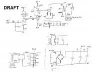
It's not a parafeed.
Here's the schematic of one of the woofer channels, as best I understand it at this point.
Here's the schematic of one of the woofer channels, as best I understand it at this point.
Attachments
Last edited:
Based on the photo..... The E-I laminations look to be a 2" stack of M6 29 gauge 150 size...with a 1:1 alternate interleaving...this would indicate that it can not tolerate any significant DC offset.... Therefore I would conclude it has a LC ...ie capacitor DC blocking.. unless I am looking at the PT in that picture ???
Hmmmm, sure looks like that would need an air gap in the OT. There are special I laminations that have a center/side cutout gap that can be used to make an air gapped E-I xfmr. with close packing (no visible gap on the outside of the OT) But one would expect those to be stacked with the I laminations all on one side. Your xfmr appears to have interleaved laminations. ?????
The only way to tell if there is a gap would be to measure the primary inductance at some reasonable AC excitation. Typical L meters use a very small test signal where lamination permeability would be low. I would put 24 VAC 60 Hz across the primary and measure the AC current. Can calc. the inductance from that. (be sure to use the primary for this test, AC on the speaker windings could generate some dangerous high voltages on the primary side) A non-gapped OT will show hundreds of Henries of L primary, while a gapped one will likely be in the tens of Henries.
Another (distant) possibility would be the use of a DC current source across one of the secondary windings to neutralize the DC primary cu;rrent in the OT. Probably some well-heatsinked power transistor used for that and a LV DC power supply for it.
Last edited:
Smoking amp, how do I do this? Can I put say a 1 ohm resistor in series with the primary to measure current? I assume I need some sort of resistor load on the secondary for current to flow on the primary? Or should the secondary be unloaded? Once I measure current what math do I use to get primary inductance?
unless I am looking at the PT in that picture ???
It's one of the output transformers.
A one Ohm series resistor should work fine to measure the AC current. Leave the secondaries un-connected.
XL = Vac / Iac
XL = 2 pi f L
so L = ( Vac / Iac ) / ( 2 pi 60 )
If the Vdrop on the 1 Ohm resistor is too small to read accurately (DVM), use a higher sense resistor. With a much higher sense resistor you could also read the Vac directly across the primary to eliminate the Vdrop factor due to the sense resistor.
Last edited:
Do you have a variac ???
Typically I use the 120V AC mains across the primary.....with a multimeter in SERIES set to AC mA .... Then I have another meter across the primary to measure AC volts.... 120V is safe for like almost any OT.... ..if you do the math you will see how ideal this is..
Then just divide the Voltage by Current then divide that by 377 and you have the inductance ...unless your outside the US...LOL...
Last edited:
I've measured an EDCOR CXPP100-MS-4.2K (100 Watt P-P) OT here for comparison. (using a Variac and two DVMs for Vac and mA AC as cerrem mentioned)
This has the same size core and 4200 OHM Zpri as the one kward has.
L is measured across the full primary. (for the more usual center tap to outer leg, divide L by 4)
Vac = 1 V, L = 106 H
Vac = 3 V, L = 265 H
Vac = 5 V, L = 379 H
Vac = 10 V, L = 530 H
Vac = 24 V, L = 799 H
Vac = 48 V, L = 981 H
Vac = 100 V, L=1020 H
Vac = 120 V, L = 1224 H
Vac= 145.4 V, L = 1285.6 H
Last edited:
Looks like the CXPP100-MS-4.2K hits a maximum L (full primary) of 1782 H at 40 Vac across the 16 Ohm winding. (equiv to 648 Vac across the full primary)
(I measured from 8 Vac to 60 Vac across the 16 Ohm winding, in small steps, to find the peak)
And 40 Vac on the 16 Ohm winding is also the max 100 Watt power rating. Apparently that's how they designed it.
However, at 27 Vac across the 16 Ohm winding, a current spike (on scope, current probe) just begins to form. This is likely where the butt joints in the laminations begin to restrict the magnetic flux. 27 Vac on the 16 Ohm winding would correspond to 45.5 Watts (at 60 Hz!!). So if you want low xfmr dist. you should cut the power rating of a typical E-I OT by half or MORE (for 20 or 30 Hz). OR, make sure the power tubes have very low output impedance. (local/partial N Fdbk recommended)
Last edited:
Excellent! Now I have a known good OPT of same core size to compare numbers against. I'll report back later after I've run the measurements on my sample. I can even duplicate the Vac voltage steps you did there, smoking amp. That is assuming my variac goes up to 145V AC.
I checked the primary Ohms on the Edcor CXPP100-MS-4.2K OT here and I get 88 Ohms and 100 Ohms either side of the center tap primary. (68 and 70 Ohms for the Northlakes Eng. OT) So the Northlakes either has more interleave winding layers or has compensated wire sizes to get better matching.
With the presumeably fewer turns (assuming the full bobbin area is used on both) for the lower Ohms, the Northlakes may be specked at 30 Hz rather than 20 Hz for low end. (not that the Edcor really makes 20 Hz, it's magnetizing current is a near square wave at 30 Hz & max voltage; and then spiky at 20 Hz) Well, I guess these things are specked with some dB of rolloff. I would call the Edcor flat to 30 Hz, maybe some dB lower at 20 Hz with obnoxious distorted magnetizing current at full power there.
When you look at real E-I OT's, you realize how important low Zout is from the power tubes. (toroids can do much better, but need -Accurate- DC balance or even -worse- things happen)
Another quality check would be to measure the leakage L for these OTs. Short the secondary, and measure (with an L meter) residual inductance across each side of the primary. These should be near equal and low mH's. Checking the Edcor, I get 14 mH on either side of the primary. That is WAY better matched than I expected!!
I have checked some others, and one side was much higher, almost flapping in the breeze.
Last edited:
Northlake OPT primary inductance measurements using 60 Hz excitation.
Method of evaluation: I don't have an AC ammeter, so I placed an 8.0Ω non inductive wire wound resistor in series with the input, then adjusted the variac till I read the Vac voltages listed below across the primary leads (not across the variac output), then measured AC (rms) voltage drop across the 8Ω resistor. Then calculated current through the primary, then calculated the inductance.
Vac = 24V, L = 84 H
Vac = 48V, L = 145 H
Vac = 100V, L= 192 H
Vac = 134V, L = 218 H
Does the size of the current sense resistor affect measurements? Indeed it does. Replacing the 8.0Ω current sense resistor with a 0.39Ω wire wound current sense resistor (this one is not non-inductive). (Measurement of this resistor fluctuates between 0.3Ω and 0.4Ω on my meter, so I will assume 0.39Ω as stamped on the side of the resistor):
Vac = 134V, L = 16H
I am pretty sure these were custom ordered OPTs. The original owner/builder of these monoblocks must have specified them to be wound with a gap so they could be used in a single ended application. Indeed the schematic retrace I previously attached does show them being used in SE fashion with no method taken to compensate for DC current (no parafeed, no current compensation on the other half of the primary winding).
So I assume these are okay to use in a single ended application. But is there a different way to interpret these results?
FYI I performed all measurements twice so I am fairly confident in their accuracy, at least to the accuracy of my hand held digital volt meter.
The 10X lower inductances would indicate a SE OT with a gap.
However, changing the sense resistor should not affect the measurements other than stressing the sensitivity limits of the Vac meter across the sense resistor. Can the meter resolve the tiny voltages seen across the 0.4 Ohms?
One thing I notice is that 8/0.4 = 20 roughly the ratio between the results: 218/16 = 13.625 Could there be a math error here plus some small measurement error across the tiny 0.4 Ohm sense resistor?
Do you have any information on the max power output of the amplifier? 100 Watts or 25 Watts? This being roughly the typical power ratio for P-P versus SE for the same size OT. A frequency response spec for the amplifier might also give some hint. The SE design typically being more narrow banded, especially the low end.
With interleaved laminations that would rule out the side gapped I and E, or E lams with slightly shorter center tongues.
The gaps would have to be in the center of the winding bobbin. So the I's become short T's and the E's become an E with a half length tongue. That way all the gaps align no matter which way the lams are inserted. External appearance is the same as a dense P-P interleaving. A dental X-ray might be able to see the gap in the core center.
The center core gap makes for a gapped OT that is not sensitive to external magnetic fields, nor does it radiate magnetic fields. Clearly an above average OT. It may have other winding enhancements.
Last edited:
I am convinced that it is PP OT...
The short tongue E lams are not common and would cost a lot to get custom made...
Even if you had the gap in the center as you stated...there is no way to provide precise control of the gap for adjusting it during manufacture...
The short tongue E lams are not common and would cost a lot to get custom made...
Even if you had the gap in the center as you stated...there is no way to provide precise control of the gap for adjusting it during manufacture...
It very well could be precision error in measuring small voltages on my meter, which supposedly has resolution of 1mV AC but I don’t know if I believe that. One day I need to get a more precise AC true rms bench meter. I’ll run the two 134V tests with the two sense resistors again tomorrow night with a fresh battery in my meter.
Pretty sure these are 25 watt amps. Tell tale indicator would be plate voltage. The PS design stacked three caps in series with voltage equalizing resistors. These are oil caps and I assume they were rated at 500V or greater each. I expect the plate voltage was about 900 to 1000 volts. With a 4.2K primary that means what about 20 watts output. However the design was direct coupled from driver to 854 grid so I suppose it could have drove them into A2 territory.
Pretty sure these are 25 watt amps. Tell tale indicator would be plate voltage. The PS design stacked three caps in series with voltage equalizing resistors. These are oil caps and I assume they were rated at 500V or greater each. I expect the plate voltage was about 900 to 1000 volts. With a 4.2K primary that means what about 20 watts output. However the design was direct coupled from driver to 854 grid so I suppose it could have drove them into A2 territory.
Last edited:
Any tube friendly dentists around the area there?
If you have a scope with a current probe (or use a current sense resistor) one could look at the magnetizing current waveform of the OT as the secondary AC voltage is increased from zero to a little beyond the max volts for 25 Watts from that secondary impedance. (careful !!, scope grounds are not generally isolated from the power ground, use an isolation xfmr with the Variac). The primary will also develop dangerous voltages, insulate the wire ends.
A P-P OT will develop a small square wave current around half power, and then develop current spikes around the square wave corners as max voltage is approached. An SE OT should develop a near sine wave magnetizing current throughout the use-able range, but of max magnitude comparable with the spikes in the P-P OT at max voltage.
Last edited:
- Status
- Not open for further replies.
- Home
- Amplifiers
- Tubes / Valves
- PP output transformer for an SE 845