I am in the process of designing a KT66 Ultralinear PP *HI-FI* amp. Instead of just copying an existing design (mostly) resistor for resistor like I have on my two previous projects, with this one I am doing a *little* bit of the math and a lot of trial and error to come up with something that I can say I did most of the leg work on.
That said, I have been drawing a series of load lines comparing a few different operating conditions to decide what OPT to buy.
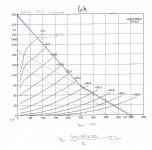
I have attached my two AC load lines that I've drawn, here are the operating parameters:
B+ 455v
8k load:
Bias -42v
Iq: ~50mA
Pout: 40.6W
6k load:
Bias:-43v
Iq: ~57mA
Pout: 42.5W
Both were biased for about 75% PD, or about 22.5w at idle.
I have read that for hi-fi applications, the class B load line should be right through, or just above the knee of the 0v grid line. Holding B+ constant as I have, aside from an extra ~1.5w of output, what is the impact of moving the load line further away from the knee?
If anyone has any other suggestions or comments on my load lines, things I might try, etc., they are appreciated.
That said, I have been drawing a series of load lines comparing a few different operating conditions to decide what OPT to buy.
I have attached my two AC load lines that I've drawn, here are the operating parameters:
B+ 455v
8k load:
Bias -42v
Iq: ~50mA
Pout: 40.6W
6k load:
Bias:-43v
Iq: ~57mA
Pout: 42.5W
Both were biased for about 75% PD, or about 22.5w at idle.
I have read that for hi-fi applications, the class B load line should be right through, or just above the knee of the 0v grid line. Holding B+ constant as I have, aside from an extra ~1.5w of output, what is the impact of moving the load line further away from the knee?
If anyone has any other suggestions or comments on my load lines, things I might try, etc., they are appreciated.
Attachments

If your load line is below the knee what happens? Look at the grid line, anode voltage and current drops this means your screen grid is now above Va and starts pulling more current as electrons coming off the cathode are now drawn to the screen grid and not the anode. If the OP stage is not designed properly your valve will suffer and may die. That and THD goes up as the valve is in a non linear region.
Your 6k line is good, well above the knee, the 8k still ok but not as good. The other consequence of the screen grid pulling too much current is increased distortion as mentioned, if you want to really get into the maths look at Radiotron Radio Designers by F Langford,it goes into some heavy maths but with practice it gets easier and less daunting.
Or you can skip that bit and just use the figures off the datasheet that correspond to whatever DC conditions etc you have. The really interesting bit with designing your own valve amp is what you do before the OP stage, what phase splitter, how much feedback etc, that's where most of the aural manipulation lies, though waht OPT you use & where you bias the OP stage matters obviously.
When choosing an OPT, get the biggest you can afford, so for a 25w amp, buy a 50w or even a 100w rated beastie.
Andy.
Last edited:
Surely I'm not intenting to scare you, but your calculations show way too much output power. You need to calculate with the difference between peak plate current and idle current.
Best regards!
Best regards!
Surely I'm not intenting to scare you, but your calculations show way too much output power. You need to calculate with the difference between peak plate current and idle current.
Best
regards!
It's a PP, you can see that from the double slope accounting for class A-B transition.
I think Pout estimate is rather reasonable considering the high plate voltage.
I would personally go for 6K as it enters a more linear region a high power delivery. I found it easier to optimize for lower distortion but it might just due to my personal approach...
Surely I'm not intenting to scare you, but your calculations show way too much output power. You need to calculate with the difference between peak plate current and idle current.
Best regards!
It's a PP, you can see that from the double slope accounting for class A-B transition.
I think Pout estimate is rather reasonable considering the high plate voltage.
I would personally go for 6K as it enters a more linear region a high power delivery. I found it easier to optimize for lower distortion but it might just due to my personal approach...
Thank you, that was the observation I had made, but being relatively new to this aspect of design, didn’t want to jump to the wrong conclusion.
From a discussion standpoint, I would assume that there is a tipping point where lowering the load impedance causes distortion to increase, as the slope of the load line increases. I ask this because I’ve seen some using a 4.3k ohm load with these tubes. It was this range of impedances I ran across in my reading that has led me to this discussion in the first place.
Your 6k line is good, well above the knee, the 8k still ok but not as good. The other consequence of the screen grid pulling too much current is increased distortion as mentioned, if you want to really get into the maths look at Radiotron Radio Designers by F Langford,it goes into some heavy maths but with practice it gets easier and less daunting.
I have casually read through it a bit. It isn’t that I’m not capable of the math, but the last time I really used anything beyond general algebra and geometry was about 15+ years ago, so I’m more than a bit rusty.
Or you can skip that bit and just use the figures off the datasheet that correspond to whatever DC conditions etc you have. The really interesting bit with designing your own valve amp is what you do before the OP stage, what phase splitter, how much feedback etc, that's where most of the aural manipulation lies, though waht OPT you use & where you bias the OP stage matters obviously.
When choosing an OPT, get the biggest you can afford, so for a 25w amp, buy a 50w or even a 100w rated beastie.
Andy.
That’s what I’ve been doing so far, pulling from data sheets and adjusting them for my design goals. I’m trying to get a little deeper into the “why” with this build.
I’ve been breadboarding the input and phase splitter on the bench, with a 6SJ7 for the input stage and 6SN7 LTP for the splitter. Probably going to try a paraphase and cathodyne as well to compare and contrast the results.
Just got an order in from Mouser with the components for a CCS for each. I’ve reached the point where I need to have an output stage handy to introduce feedback to tweak the required gain of the input stages.
I’m probably looking at the Hammond 1650P or Edcor CXPP60-6.6k. Likely leaning towards the Hammond due to availability unless someone has some A/B experience that makes it worth waiting for the Edcor.
Yes, people use 4.3k with these tubes, but at a lower B+. In ultra linear, the relationship between B+ and Vg2 is fixed - there is one (or small range) of load line that will work well at a given voltage. In pentode you can simply adjust Vg2 so the knee is where you want it to work with a given B+ and load impedance. It’s a lot harder to change the screen tap on an OPT. You get 43%, and sometimes 23.
You also have to consider your voltage regulation. Do you want the optimum load at your unloaded or fully loaded voltage? How much difference is there between the two? Depends how loud you will be playing. Yet still more design decisions.
Screen stoppers will prevent g2 meltdown when driving into the knee - if you make it large enough. Unfortunately, the larger you make it the more distortion there is. Even with the 6.6k you’ll drive it there if your load line is elliptical (reactive) or at bass resonance so having some sort of screen stopper is a good idea.
Hammond vs EDCOR - been struggling with that myself. I’m usually thinking 4 or 5 projects ahead of where I am at the moment and considering what to order the next time the credit card balance hits zero. I’ve got an EL 34 project in planning (a quad of winged C Svetlanas on hand) and I’m custom winding the power transformer now. Got to figure out which OPTs to buy.
From a discussion standpoint, I would assume that there is a tipping point where lowering the load impedance causes distortion to increase, as the slope of the load line increases. I ask this because I’ve seen some using a 4.3k ohm load with these tubes. It was this range of impedances I ran across in my reading that has led me to this discussion in the first place.
At high power delivery I would go for the 6 K because it works in a more linear region. Remember that speakers are not resistive so you need a reasonable linear area where tubes work in a linear fashion. At low power it's more a balance of quiescent current and good balance between the two halves for a given load. If the quiescent current is too low you will get worse linearity regardless of the load (the composite tube plate curves will depart more from being straight lines as it should be ideally). So if you decrease the load too much you will find the limit where you cannot go below a certain threshold because the current you need is too high. But 4.3K might be still ok, I think. I cannot tell for sure because I do not know this tube very much. Especially current production.
You can optimize empirically with an oscilloscope and a square wave source signal at around 40 Hz. Normally if you do this at low frequency it will work at any audio frequency, unless the transformer has parasitics issues and is not well balanced at high frequency. You will see that the square wave in reality is not perfectly flat and has a slope but that's only because of the limited primary inductance. It's normal. What you need to look at is how straight are the lines. When the amp is well balanced you will get straight lines. This might likely result is some small DC unbalance but that's easy fix, using a transformer with small airgap.
Transformers with EI cores usually have a small gap by default that will cope with some 5 mA easily for the size you need here. C-cores transformers are usually the more expensive ones and manufactures typically declare the possible DC unbalance the transformer can take without compromising anything else.
Toroidals are the least tolerant in this regard but 1-2 mA should still be possible in most cases.
The Hammod should be a good choice.
Last edited:
I (likely) will have a very stiff supply. I picked a 800v CT transformer weighing in at almost 14# (no clue what it came out of, but it is a beast) from an estate sale a few months ago and plan on using a choke input to knock the B+ down to what I require. That too should give me very good regulation.
I am likely going to stick with the ultra linear design right now, when I was considering pentode mode I have some LR8s on hand I was going to use to regulate the screens. They may see some use elsewhere in the project, maybe to regulate the preamp supply.
I am likely going to stick with the ultra linear design right now, when I was considering pentode mode I have some LR8s on hand I was going to use to regulate the screens. They may see some use elsewhere in the project, maybe to regulate the preamp supply.
- Home
- Amplifiers
- Tubes / Valves
- PP Load line optimization questions