Quarantine forces me to resume a long ago forgotten project. Twentyish years ago I bought tubes and transformers for an EL84 PP project. To make things easier (maybe) I ordered one of these 6N4 / 12AX7 + EL84 / 6P14 Push-pull Tube Power Amplifier 10W+10W Stereo Amp PCB 699998773739 | eBay
It's on the way, but I was wondering about the power supply. I have a Hammond 272HX which will give me 600VCT. Worries my B+ will be too high with the 220mfd and 6.8.k on the power supply?
It's on the way, but I was wondering about the power supply. I have a Hammond 272HX which will give me 600VCT. Worries my B+ will be too high with the 220mfd and 6.8.k on the power supply?
I have a Hammond 272HX which will give me 600VCT. Worries my B+ will be too high with the 220mfd and 6.8.k on the power supply?
Download PSUD2 and play with values. Very easy to use software. Adjusting value of first capacitor after rectifier will allow you to adjust also output voltage. This assumes CRC or CLC filter after rectifier. CLC is better of course.
Download PSUD2 and play with values. Very easy to use software. Adjusting value of first capacitor after rectifier will allow you to adjust also output voltage. This assumes CRC or CLC filter after rectifier. CLC is better of course.
I'll do that. Thank you very much!
The PCB doesn't include the whole PS. How were you planning to build it out including rectifier(s)?
You've only spent 13 bucks so just throw it away and order a SPP board from George at Tubelab. The PS is right on the board. The 272JX will be perfect with this.
SPP Build
Get a couple of reasonable OPTs from Edcor and a bunch of parts from Mouser and Antique sound lab and you'll have a great amp.
Steve
SPP Build
Get a couple of reasonable OPTs from Edcor and a bunch of parts from Mouser and Antique sound lab and you'll have a great amp.
Steve
Quarantine forces me to resume a long ago forgotten project. Twentyish years ago I bought tubes and transformers for an EL84 PP project. To make things easier (maybe) I ordered one of these ....
May I ask what output transformers you bought? If they are high quality transformers, as I expect since you bought them two decades ago, I think you owe it to yourself to consider better circuits than the basic one employed in the ePay PCB.

One of the top-notch current EL84 PP designs is the “Baby Huey” amplifier. There was a group buy on diyAudio recently and there are some extra PCBs around. Consequently there are several BHs being built right now, including mine, so help, advice, BOM, etc., are readily available.
The Baby Huey EL84 thread: EL84 Amp - Baby Huey
The Group Buy: GB for Baby Huey PCB
A builder’s thread: Oh no...not another Baby Huey EL84 build.
BH Wiki: Baby Huey PP EL84 amplifier
You power transformer output will be too high since the BH does not use cathode bias. But you could easily sell the Hammond and buy the right power transformer for similar money. Actually a bit less if you go to Antek. Ask here, or send me PM if you have questions.
Last edited:
You've only spent 13 bucks so just throw it away and order a SPP board from George at Tubelab. The PS is right on the board. The 272JX will be perfect with this.
Steve’s suggestion is based on the same thought - if you go to the trouble of building the amp, build as good a design as you can find. I have not built George’s Simple Push-Pull (SPP) amp, and I tried to look at the schematic, but the link is broken on the Tubelab webpage. So, I don’t know if the SPP uses fixed or cathode bias, but I would assume cathode bias. The reason why your Hammond 272HX will work here is that the SPP uses a tube rectifier which reduces the power supply output voltage. Steve said he thought the SPP sounded better than the diyTube ST35 clone, which I have built and it is excellent. I expect the Baby Huey will sound better yet 😉 but we shall see 😀
It occurred to me that you probably could use your power transformer with a tube rectifier (like 5R4 to get the voltage down sufficiently) with a Baby Huey too.
The PCB doesn't include the whole PS. How were you planning to build it out including rectifier(s)?
Yes I was planning on using two of these BYT78-TR Vishay Semiconductors | Mouser instead of the BYW96E. This would then if course feed into the PCB. I ran it in the PSUD2 and it seems like it is right. Will try to post a screenshot.
May I ask what output transformers you bought? If they are high quality transformers, as I expect since you bought them two decades ago, I think you owe it to yourself to consider better circuits than the basic one employed in the ePay PCB.
One of the top-notch current EL84 PP designs is the “Baby Huey” amplifier. There was a group buy on diyAudio recently and there are some extra PCBs around. Consequently there are several BHs being built right now, including mine, so help, advice, BOM, etc., are readily available.
The Baby Huey EL84 thread: EL84 Amp - Baby Huey
The Group Buy: GB for Baby Huey PCB
A builder’s thread: Oh no...not another Baby Huey EL84 build.
BH Wiki: Baby Huey PP EL84 amplifier
You power transformer output will be too high since the BH does not use cathode bias. But you could easily sell the Hammond and buy the right power transformer for similar money. Actually a bit less if you go to Antek. Ask here, or send me PM if you have questions.
Yes it was Hammond 1608s. I know not the best I guess but they were not too expensive in 2003!
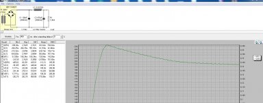
Yes I was planning on using two of these BYT78-TR Vishay Semiconductors | Mouser instead of the BYW96E. This would then if course feed into the PCB. I ran it in the PSUD2 and it seems like it is right. Will try to post a screenshot.
From PSUD2
Attachments
You've only spent 13 bucks so just throw it away and order a SPP board from George at Tubelab. The PS is right on the board. The 272JX will be perfect with this.
SPP Build
Get a couple of reasonable OPTs from Edcor and a bunch of parts from Mouser and Antique sound lab and you'll have a great amp.
Steve
Thanks Steve. I guess I kinda just wanted to use the parts I had, and the board from China just made it a little easier. Since I have the Hammond 1608's I just wanted to use them. I also at the time ordered the JJ EL84s and have been able to accumulate a variety of 12AX7s over the years. From all the passive components I do have, I'll only have to make a small $30 order from Mouse for the rest of the resistors and caps I need. I did come across the Baby Huey posts AFTER I ordered the board, wish I had done that sooner!
It is probably correct that you end up burning away too much voltage with resistors if you need only 300V B+. If your transformer had two center leads, you could have used the two windings in parallel with a full wave bridge rectifier. But I guess the Hammond doesn't have that. Maybe it would be possible to use only one half of the windings (0-300V) with a bridge rectifier? Not sure if that would overload the transformer (possibly).
IMHO, center tap transformers should be used with tube rectifiers or circuits that need + - voltages. Otherwise transformers with single secondary winding is better with a full wave bridge rectifier (better utilization of transformer).
IMHO, center tap transformers should be used with tube rectifiers or circuits that need + - voltages. Otherwise transformers with single secondary winding is better with a full wave bridge rectifier (better utilization of transformer).
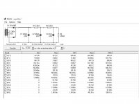
From PSUD2
You are only running the simulation for a fraction of a second, or 1 millisecond. Run it at least 5000 ms.
And you can't have that many 6k8 resistors for B+. You end up with no voltage at all. The main B+ in circuits such as this one have two RC filters with 100 ohm 10W resistors. The 6k8 resistor is for the lower voltage to the 12AX7 in the input/phase splitter.
And your R3 should simulate the full load of two EL84 + the smaller current to the 12AX7, so put something like a 220 mA current sink instead as suggested in the schematic (I don't know exactly how much that circuit needs).
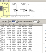
I think 300V is the right way to model a 300 0 300 transformer with that rectifier circuit
You are probably correct. I haven't used CT transformers at all. Then it might look better. You still have to watch how much power the resistors burn away. Just multiply the RMS voltage and current that is shown in PSUD over the resistor.
Last edited:
Yes I was planning on using two of these BYT78-TR Vishay Semiconductors | Mouser instead of the BYW96E. This would then if course feed into the PCB. I ran it in the PSUD2 and it seems like it is right. Will try to post a screenshot.
OK, again you are following the schematic which is nothing like the PCB. The PCB has a spot for the 47uF cap, 2 6.8K resistors, 1/channel, and 2 22uF caps, 1/channel. I ask again, how were you fully planning to build this out?
Complete build series
I'll toot my own horn, others toot theirs. Here's the complete build series I did for beginners on the Wall of Sound.ca site.
DIY EL84 Amp Update! | Wall of Sound | Audio and Music Reviews
DIY EL84 Amp Project: Part 2, Circuit Board and Chassis Preparation | Wall of Sound | Audio and Music Reviews
DIY EL84 Amp Project: Part 3, Circuit Board Assembly | Wall of Sound | Audio and Music Reviews
DIY EL84 Project, Part 4: Chassis, Board and Transformers, Integration and Wiring | Wall of Sound | Audio and Music Reviews
DIY EL84 Project, Part 5: Optional Volume Control and Input Switch Assembly, Power-Up and Testing | Wall of Sound | Audio and Music Reviews
https://wallofsound.ca/audioreviews...ion-sonic-evaluation-and-output-mode-options/
- Home
- Amplifiers
- Tubes / Valves
- PP EL84