Interesting project.
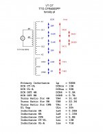
What is your turn ratio between CFB and primary?
one CFB winding = 0.1*Np/2 (10% of a half primary)
I also SPICE'd UL+ CFB PP amplifier (with LTSPice ), yet not proceed to prototype. I've got optimal results with 12 - 15% CFB.
Source of THD Analyzer:
Audio Total Harmonic Distortion Analyzer for LTSPICE, making THD vs. Amplitude and Frequency sweeps in LTSPICE | Audio Perfection
Short forum thread:
LTSPICE THD Analyzer
Source of THD Analyzer:
Audio Total Harmonic Distortion Analyzer for LTSPICE, making THD vs. Amplitude and Frequency sweeps in LTSPICE | Audio Perfection
Short forum thread:
LTSPICE THD Analyzer
Last edited:
Which does not seem to correspond to the value used in your sim.one CFB winding = 0.1*Np/2 (10% of a half primary)
It looks like KT77 is the winner when we want the lowest distortion in PP amp.
Modern Tubes in the UL40-S2
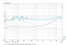
This is a thd comparison of super-pentode and super-triode at 25W/4R5 in my PP1 with KT77JJ (bias 35mA)
Modern Tubes in the UL40-S2
This is a thd comparison of super-pentode and super-triode at 25W/4R5 in my PP1 with KT77JJ (bias 35mA)

I looked at the simulation again (post 54), it was correct, so, my last OPT schematic is wrong (post65).
This is the simulation of the OPS . CFB and TRIODE connected KT88 don't like each other. In terms of distortion, super-pentode is the best (also the gain is the highest, the global NFB will be the strongest). When considering output impedance as well, super-triode is a best choise.
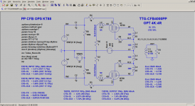
This is the simulation of the OPS . CFB and TRIODE connected KT88 don't like each other. In terms of distortion, super-pentode is the best (also the gain is the highest, the global NFB will be the strongest). When considering output impedance as well, super-triode is a best choise.

From those voltages one can conclude Raa=4k8 and the UL-tap is at 40%.right, and now ?
The Raa is not 4k since the cathode winding is part of the anode-cathode load.And also the cathode winding adds to the UL part of the anode side.
Even with no UL tab there is a small amout of UL by the cathode winding.
Mona
Kt88 from Tung sol are very good...
From EH I have no clue...
KT77 is not to be underestimated, they are true pentodes not like el34 and should perform ultimately well in UL with cathode feedback, it is in fact a new design that I want to push to 60 or 70 watts with 1% thd if possible...
My input on the explanation of the higher THD of the KT88 which makes no sense since it is way bigger tube than kt77 is simple.
In my experiments of THD analysis with KT88 I found that they didn't perform that well under 50 watts versus other smaller tubes. But at 50 watts they are very strong performers.
I think for the test to be valid you should do it again with 50 watts, 10 watts is like too little for Kt88 to show what they can do, in my tests they beat kt120 at that wattage, at 80 watts kt120 are ok, kt88 are clipping
(for the THD figures, I obtained way better thd with 0.21 THD at 10 watts with EL34 with a not CFB, only with a basic 25 watts edcor transformer, with KT77 I can obtain 0.16% or less, I lost my thd sheets, and with similar 13 db feedback, and my power supply is un-regulated.)
Last edited:
PP1 AMPLIFIER MEASUREMENT RESULTS
=========================
TEST CONDITIONS: B+ 400V, Global NFB 10-15dB (OPS configuration and tube dependent)
BEST OPS CIRCUIT per TUBE (in terms of distortion, dummy load 4R5)
********************************************************
EL34EH, BIAS 40mA
-----------------------
1. CFB+UL (best)
2. CFB+ULX
3. CFB+TR
KT77JJ, BIAS 40mA
----------------------
1. CFB+TR (best)
2. CFB+UL
3. CFB+ULX
KT88EH, BIAS 60mA
-----------------------
1. CFB+ULX (best)
2. CFB+UL
3. CFB+TR
BEST OVERALL CIRCUIT and TUBE
***************************
THD 10W/4R5/1kHz
----------------------
1. KT77JJ CFB+TR - 0.06%
2. EL34EH CFB+UL - 0.1%
2. EL34EH CFB+ULX - 0.1%
2. KT88EH CFB+ULX - 0.1%
3. KT77JJ CFB+UL - 0.15%
THD 25W/4R5/1kHz
----------------------
1. KT88EH CFB+ULX - 0.13%
2. KT77JJ CFB+UL - 0.15%
3. EL34EH CFB+ULX - 0.22%
(no CFB+TR here, 25W is a clipping region)
CFB+TR = CFB+TRIODE
CFB+UL = SUPER-TRIODE
CFB+ULX = SUPER-PENTODE
Last edited:
“KT77 is a beam power pentode with octal base. So it can be used in most EL34 amplifiers. It has more power, fatter bass and more headroom than the EL34 and E34L while providing very detailed tones.” is not a true pentode
Ah OK, but what is not true is what they STATe in their website!!! It's not me. I had not noticed your reply in that thread. So Peter was right. I asked directly to Toroidy about that funny definition and they replied that it was indeed 10% Ra. Now it's clear that they do NOT know what they are talking about. I have to admit that Peter was right and they have probably copied the Plitron transformer. Bad copy of course, because the Plitron has quite better bandwidth and headroom.
I’m following this thread with great interest and trying to learn about CFB. Sorry but I did not follow your logic here. Would you kindly explain so a relative newbie could understand.
1. Why is the Toroidy definition funny? I looked at the Plitron transformers and to me it looked they stated the % CFB in a similar way.
2. I don’t understand why did you concluded that “they do not know what they are talking about”.
3. The Toroidy transformers are about 1/2 the price of the corresponding Plitron transformers. So, how bad a copy is it? From Toroidy specs the bandwidth seems good enough for me; the Plitrons go into very high frequencies but that may not be needed. Could you explain “headroom” you mentioned.
After rereading the thread and the thread on the Toroidy CFB OT spice model I now see what you mean re my question 1 and 2.
I underestimated my HT PSU a little. It's classic CRC circuit, 240uF-15R-240uF. Even though it has quite good ripple rejection this is not enough for PP amp. Specially, when talking about OPS IMD. Let's see what I measured.
OPS PSU RIPPLE
IDLE (2x60mA) 406VDC + 1.36Vpp ripple
LOAD 10W/4R5 398VDC + 1.64Vpp ripple
LOAD 25W/4R5 394VDC + 2.08Vpp ripple
Next, I measured 10W/25W/4R5 by ARTA.
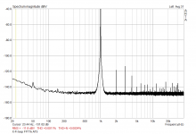
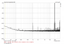
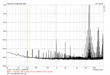
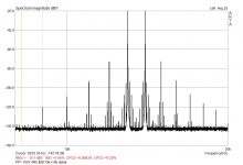
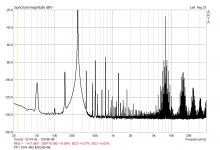
Spectrum analyze revealed the truth. Rejection of mains related frequencies are good (100dB below fundamental). But, there is awful IM distortion caused by OPS ripple interaction with input signal. IM products are 77dB below fundamental and also surround higher odd harmonics.
This IMD is not related to AC heating, LTSpice sims show the same effect and near values (heating is "DC").
Solutions
1/ Add the same ripple to the driver outputs (OPS inputs) in opposite phase and with amplitude divided by OPS gain.
2/ Use better HT PSU, like CLC
I am going to try the second one, far more easier to implement. I will use e-choke.
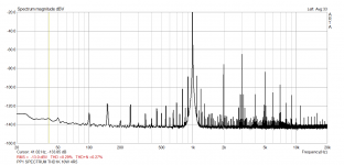
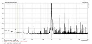


LKA - does ARTA measure specific IM response using 60/7k, 250/8k, 19k/20k test signals like REW ?
I believe your measurements relate to what is typically captured by the difference between THD and THD+N levels (where N includes anything else including hum and hum modulation of signal and its harmonics) - but perhaps you haven't set ARTA up properly, as your plots show THD > THD+N.
I believe your measurements relate to what is typically captured by the difference between THD and THD+N levels (where N includes anything else including hum and hum modulation of signal and its harmonics) - but perhaps you haven't set ARTA up properly, as your plots show THD > THD+N.
The measurement shows almost transistor like distortion, but low. This should ideally appear at saturation point only in a tube amp. Keep use posted on your results with E-chokes!
E-CHOKE
- I expect the same result as here http://www.tentlabs.com/Components/Tubeamp/page44/assets/E-choke design UK.pdf
Measurements
- ARTA can measure IMD and it was set up properly.
- Components were freely laid out on the desk, so not ideal conditions, see YouTube
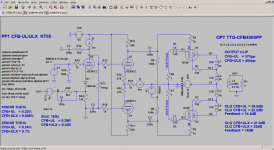
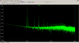
LTSpice sim
- the driver has ideal power supply
- output stage PS 400V and 2Vpp ripple, pure 100Hz sine
- load 10W/4R/1kHz


LKA, can you report the IM distortion results/plots from ARTA?
I think you will need to play around with your soundcard and ARTA settings, as there is something definitely wrong when THD > THD+N.
I suggest your point about power supply ripple and hum modulation of a test signal needs to be benchmarked as the difference between THD and THD+N, along with IMD measurements. Then the influence of changing power supply filtering can be gauged.
Last edited:
- Home
- Amplifiers
- Tubes / Valves
- PP CFB toroidy OPT
