I would appreciate any comments/suggestions/criticisms on the below schematic. I’m a self-taught hobbyist, trying to separate internet wheat from chaff; not a newbie – but I’m venturing into a couple of new things I haven’t worked with before.
A few comments on what I have going on here:
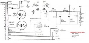
- I currently have DIY PP 6B4G AB1 amps, 93dB speakers. First goal is to stay in Class A; plus, a bit more power. Modern sources, 1.8vrms or so
- Basis is a 6EM7-300bpp no feedback schematic by GaryW (see link below)
- Mono construction
- 300b operating point 350v/85mA (each) from 1950 AT&T 300b data sheet PP Class A1 example
- Individual fixed bias on 300b’s. AC filaments
- Replaced 6EM7 triode 1 with 6J5GT, direct coupled to 6EM7 triode 2. 6EM7 triode 1 left unused
- 1:1+1 Interstage phase splitter, 35mA (same Electra-Print IT as in GaryW amp)
- LCLC supply, used PSUD II; stacked gas VR tube shunt regulation for the input/driver.
It’s a pretty basic Class A no feedback amp that really shouldn’t be that hard. Concerns I have are:
- My first time trying direct coupling; have I worked it out correctly? Looking at the 6EM7 unit 2 curves, I think I should be at 147v p-k, -23v bias, approx. 34mA, 5w dissipation
- Input 6J5GT operating point shamelessly borrowed from Komuro’s DC 300b amp schematic. Will the 6J5 and 6EM7 (triode 2) combine to give me enough voltage swing? Without a preamp?
- First time using VR tubes; am I missing anything? I’m a bit concerned about three in series striking properly.
If I’m being an idiot, just let me know 😛
GaryW amp: post #4 in this thread: http://www.diyaudio.com/forums/tubes-valves/126298-300b-push-pull-amp.html
my preliminary schematics attached:
A few comments on what I have going on here:
- I currently have DIY PP 6B4G AB1 amps, 93dB speakers. First goal is to stay in Class A; plus, a bit more power. Modern sources, 1.8vrms or so
- Basis is a 6EM7-300bpp no feedback schematic by GaryW (see link below)
- Mono construction
- 300b operating point 350v/85mA (each) from 1950 AT&T 300b data sheet PP Class A1 example
- Individual fixed bias on 300b’s. AC filaments
- Replaced 6EM7 triode 1 with 6J5GT, direct coupled to 6EM7 triode 2. 6EM7 triode 1 left unused
- 1:1+1 Interstage phase splitter, 35mA (same Electra-Print IT as in GaryW amp)
- LCLC supply, used PSUD II; stacked gas VR tube shunt regulation for the input/driver.
It’s a pretty basic Class A no feedback amp that really shouldn’t be that hard. Concerns I have are:
- My first time trying direct coupling; have I worked it out correctly? Looking at the 6EM7 unit 2 curves, I think I should be at 147v p-k, -23v bias, approx. 34mA, 5w dissipation
- Input 6J5GT operating point shamelessly borrowed from Komuro’s DC 300b amp schematic. Will the 6J5 and 6EM7 (triode 2) combine to give me enough voltage swing? Without a preamp?
- First time using VR tubes; am I missing anything? I’m a bit concerned about three in series striking properly.
If I’m being an idiot, just let me know 😛
GaryW amp: post #4 in this thread: http://www.diyaudio.com/forums/tubes-valves/126298-300b-push-pull-amp.html
my preliminary schematics attached:
Attachments
With the stabilizer tubes shunted with a capacitor, you may have build a relaxation oscillator. This is not a low noise stabilized powersupply approach. Better use no C across the stabilzer tubes, less current and go from the tubes with a series resistor to the grid of a cathode follower. There you can put a C from the grid to ground
Why a DC coupled approach? It gives less headroom at the tubes and therefore more distorsion. I consider it better larger anode resistors and AC coupling. And no transformer to drive the tubes, no reason if you don't want to drive them into grid current. Better a diff amp with a real current source in the common cathodes and a high voltage to the anode supply with larger anode resistors. There is nothing wrong with coupling capacitors if you select the correct type like PP and put the corner frequency where you want to cutt-off for rumble. Rumble and lower frequencies than you want do much more harm than a coupling cap ever can do, especially with transformators in the amp..
Also, NO decoupling caps over the cathode resistors. Better a stage more if you need more gain. That will give you less distorsion and a cleaner signal and more BW.
I know I may hurt the feelings of DC coupled fans, but this is how I think an amp should be. Sorry if you disagree
Thought I was safe with up to 0.1uF across the VR tubes?
Why DC coupled? Why not? Haven't tried it before. I can always change it later.
Transformer coupling/phase splitting - I did it in my 6B4G amps, I like the result, sticking with it for now.
Why DC coupled? Why not? Haven't tried it before. I can always change it later.
Transformer coupling/phase splitting - I did it in my 6B4G amps, I like the result, sticking with it for now.
Thought I was safe with up to 0.1uF across the VR tubes?
Why DC coupled? Why not? Haven't tried it before. I can always change it later.
Transformer coupling/phase splitting - I did it in my 6B4G amps, I like the result, sticking with it for now.
DC coulping will result in much less headroom for the vakles, so more distorsion. In addition, maintain a correct operation point is more difficult and depends much more at the valve. Also worse. That why you should not DC couple. Havn't tried before isn't a design parameter.
In the years 20, valves were also coupled with transformers, off course it workes but no reason why that should be better. Transformers are difficult and expensive parts which really should be designed very carefully for audio, interleaved winding etc. If not required, better avoid. In your diagram with quite a low voltage for the driver you will get a lot of even harmonics.
Nice circuit; I don't see many problems with headroom.
With some 1 VRMS input signal you will drive this amp to full class A power; the interstage transformer coupled driver might even give enough power to drive the 300B's into a bit A2 (however 300B's are feeling better without grid current).
Much has been said about pro's and con's of RC vs. direct vs. transformer coupling.
Some mighty fine designs are known which use inductive plate loads and interstage transformer coupling.
One example: The Karna Amplifier
And another one the Feral Eye, a 2A3 PP with 6J5 input tube and interstage phase splitter transformer: http://enjoythemusic.com/magazine/sound_practices/14/feral_eye_schematic.pdf
It is true that the transformers should be of high quality.
Last edited by a moderator:
Thought I was safe with up to 0.1uF across the VR tubes?
Why DC coupled? Why not? Haven't tried it before. I can always change it later.
Transformer coupling/phase splitting - I did it in my 6B4G amps, I like the result, sticking with it for now.
really there is nothing wrong what you doing.
but I would skip the shunt cap because the gas regulators in series like that will have a very small capacitance overall so it shouldn't be needed. if you find you do, I would try a .001 uf cap first.
headroom has to do with the voltage distance left over from measuring the peak of the signal to the dc bias that is in the same direction as the signal. For instance: In a circuit stage we measure 130VDC at the output of a stage. that voltage is considered a virtual ground in AC. Its point on the ac signal scale it is 0V ref (or zero crossing) now the ac signal can swing positive (up to cutoff at b+ potential) and swing negatively (down to clipping at DC ground). so if the B+ voltage is 260 and zero crossing is 130 V, and the output signal swings 50V positive and 50 V negative (100V p-p) there is 130V of total headroom that gives us 65V of peak signal headroom.
coupling has nothing to do with headroom. DC actually is the best coupling method because it keeps phase coherency.
A question: Why are you not using the other triode in the 6em7?
A question: Why are you not using the other triode in the 6em7?
... like this schematic's first two steges.
Attachments
not too bad.... like this schematic's first two steges.
but I would work out the first stage depending on what is driving the amp instead of a generic input.
I notice that there is a lot of diy designs here without grid stoppers. What is up with that?
Are people are in a false sense it does bad things to the signal?
I also noticed the trend of badly designed power supplies here too.
I'll omit the cap across the VR tubes when I breadboard it, then gradually add to see what happens.
I'm not using the other triode in the 6EM7 because it just doesn't sound very good. And too much gain. I don't mind the extra socket, and extra tube.
Thanks everybody. Keep 'em coming!
edit - forgot to add grid stoppers in drawing up the front end. Oops. I always use them now. Had LOTS of fun with 5842's once...
Last edited:
I've gotten 6em7's to work on by them selves. They sound great when they are set up properly. Someone about a decade after I stop building those single tube amps nicknamed them "spud amps"
I'll give the first triode a try when I breadboard. Might as well to see if I like it. Maybe leave the cathode resistor unbypassed to bring down the gain.
the first triode is described as 6SL7 like; isn't a 6SN7 type more linear? Assuming the added gain isn't needed.
Thanks again, everybody
the first triode is described as 6SL7 like; isn't a 6SN7 type more linear? Assuming the added gain isn't needed.
Thanks again, everybody
If you don't need the gain then the 6DN7 provides a medium-mu dissimilar triode alternative that is very linear:
http://tubedata.tigahost.com/tubedata/sheets/093/6/6DN7.pdf
http://tubedata.tigahost.com/tubedata/sheets/093/6/6DN7.pdf
If you don't need the gain then the 6DN7 provides a medium-mu dissimilar triode alternative that is very linear:
http://tubedata.tigahost.com/tubedata/sheets/093/6/6DN7.pdf
If only the large triode were the same; I really want to stick with the 2A3 like large triode of the 6EM7
And no, I don't want to mess with a real 2A3. At least for now.
- Status
- Not open for further replies.
- Home
- Amplifiers
- Tubes / Valves
- PP 300b project (3 stage)