Hey Anyone,
I'm currently building a push pull 2A3 amp for a friend. Its a mono amp that he wants to use to listen to 78's.
I've never worked with DHT tubes before and have a question. (The front end will be Pete Millet's Uniamp.) I want to use fixed bias because it results in a little more power and half the distortion. I know how to apply the bias voltage between the coupling cap the grid stopper. But how do you measure the current?
I mean the DC supply must ground through the 2.5 volt heater circuit right? And if I connect a resistor to ground between the two tube's heater supply any measurement across that resistor will be for both tube's DC component as well as some unknown quanity of AC cuurrent as well. Can anyone tell me how to do this? Or lacking that, point me to a PP 2A3 schematic?
Kevin
You can use two DC supplies and 10 ohms to earth. I have 105Db speakers and no problem using AC with 2A3's.
You can always measure the Dc current after measuring the ohms from CT to plates. Or you can put 1 or ten ohms resistors to the plates.
Phil
You can always measure the Dc current after measuring the ohms from CT to plates. Or you can put 1 or ten ohms resistors to the plates.
Phil
Thanks Phil,
Using the known resistance of the OPT primary half windings never occurred to me. (An elegant solution.) But what about a cathode resistor? Can I just let the DC ground through the power supply? It seems even If I put in a cathode resistor some of the DC will still go through the filament supply?
Kevin
Hi,
If using fixed bias on the 2A3's, just tie the 2.5v transformer's Center Tap to ground. If your 2.5v transformer doesn't have a CT, then get two 10 ohm resistors and attach one to each of the 2.5v leads. The loose ends of these 2 resistors get tied together and this connection then goes to ground. You will need two filament supplies per channel if you want to measure current with a "cathode" resistor. The OPT winding resistance method is the easiest way to go to measure each output tubes current independently.
The DC will only go through to where your filament supply is attached to ground. The filament heater supply and 2A3's ground return path are 2 different circuit paths.
2A3's in PP with the driver RC coupled to the 2A3's will realistically give you about 8 watts out before it poops out. You can raise this to 14-15 watts out, if you use an interstage transformer or cathode follower to drive the 2A3's. All this is assuming class "A" operation at 250 volts B+ with fixed bias for the 2A3's.
Last edited:
in the two SET amps that i built out of the 2A3, one unit has 2.5 volts ac with center tap, and the other used a humdinger pot. in both cases i found that just setting the pot to center in one and just using the center tap in the other did not produce hum issues...
btw, my operating point was 250 volts plate and biased to -45 volts grid resulted in a plate current of 60mA, spot on with published specs for the pairs of Shuguang tube i used, truly matched characteristics.... 😀
btw, my operating point was 250 volts plate and biased to -45 volts grid resulted in a plate current of 60mA, spot on with published specs for the pairs of Shuguang tube i used, truly matched characteristics.... 😀
Here's a nice Hammond transformer which just happens to have two 2.5v @ 2.5 amp windings and a bias tap and a 5v rectifier winding!
http://www.hammondmfg.com/pdf/EDB302AX.pdf
Should be available from digikey.
http://www.hammondmfg.com/pdf/EDB302AX.pdf
Should be available from digikey.
Hey Anyone,
I'm currently building a push pull 2A3 amp for a friend. Its a mono amp that he wants to use to listen to 78's.
I've never worked with DHT tubes before and have a question. (The front end will be Pete Millet's Uniamp.) I want to use fixed bias because it results in a little more power and half the distortion. I know how to apply the bias voltage between the coupling cap the grid stopper. But how do you measure the current?
I mean the DC supply must ground through the 2.5 volt heater circuit right? And if I connect a resistor to ground between the two tube's heater supply any measurement across that resistor will be for both tube's DC component as well as some unknown quanity of AC cuurrent as well. Can anyone tell me how to do this? Or lacking that, point me to a PP 2A3 schematic?
Kevin
If you have experience with valve amps (as it seems to me) and do things carefully the easiest way is: put a 1 ohm precision resistor between each plate and its primary OTP connection. Read the voltage drop with a DC meter and each millivolt you get will equal to 1 mA.
Last edited:
Hey All,
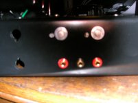
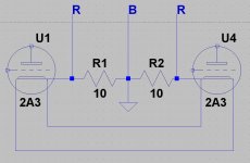
Having put the cart before the horse I'd already installed the taps and pots to adjust the bias voltage. (See photo) I've used this system before with non-dht valves. Problem is if I attach it to the center tap and the end taps the jacks will expose the user to @300 volts DC. So I have to attach it to the cathode side. I've also attached a drawing that I think will work without the high voltage. As multi suggested above.
Having put the cart before the horse I'd already installed the taps and pots to adjust the bias voltage. (See photo) I've used this system before with non-dht valves. Problem is if I attach it to the center tap and the end taps the jacks will expose the user to @300 volts DC. So I have to attach it to the cathode side. I've also attached a drawing that I think will work without the high voltage. As multi suggested above.
Attachments
Last edited:
If you are going to use a common filament winding (as your wiring diagram seems to indicate) you will not be able to measure the bias setting to each tube individually. You would have to have a separate winding for each tube. I have a PP 2a3 amp, cathode biased, and I feed each 2a3 with its own CT transformer, and connect the center tap of each to a cathode resistor. If you wish to use fixed bias and have the ability to measure each tube individually, I would suggest using a similar arrangement, a 10 ohm resister from center tap to ground of each tube would allow you to read each tubes bias separately. If you are going to use a common winding for both tubes, use its center tap to feed a 5 ohm resistor to ground, would allow you to read the bias current in ma for each tube in ma, but they would be biased as a pair ( ie a reading of 50mv across the 5 ohm would indicate each tube is running at 50 ma, assuming they are a matched pair). I personally do not care for schemes that require measuring the B+ side - too easy to make a mistake. If you have two bias pots installed, and want to have the ability to set each tube, you will have to have two separate filament supplies, each with either a center tap, or a derived center tap using a pair of resistors from each side of the filament to ground.
Thanks, I now have a plan. I found a 2.5 volt 3 amp transformer made by Hammond. Angela sells it for $14.
Jim, To measure current I would need the voltage dropped across a resistor. So why a pair?
Jim, To measure current I would need the voltage dropped across a resistor. So why a pair?
if using a 2.5 volt heater winding with ct. 1 resistor to the ct is enough.
if no center tap then 2 resistors on either side of the filament...
links....ÖØÎÂ15ÄêÇ°¾ÉÃΣ¬ÊÔÑé 2A3 PP£¬¿´¿´ÉùÒôÓжàÉÙÎüÒýÁ¦£¿£¨#22¸üеç·ͼͬʱ¼æÈÝ300BPP£© - µ¨È¤ÍøÂÛ̳ - Powered By BBSXP
http://www.bonavolta.ch/hobby/en/audio/2a3_4.htm
Application Notes : 2A3 Push-Pull Power Amplifier
if no center tap then 2 resistors on either side of the filament...
links....ÖØÎÂ15ÄêÇ°¾ÉÃΣ¬ÊÔÑé 2A3 PP£¬¿´¿´ÉùÒôÓжàÉÙÎüÒýÁ¦£¿£¨#22¸üеç·ͼͬʱ¼æÈÝ300BPP£© - µ¨È¤ÍøÂÛ̳ - Powered By BBSXP
http://www.bonavolta.ch/hobby/en/audio/2a3_4.htm
Application Notes : 2A3 Push-Pull Power Amplifier
Will the DC voltage dropped across one of the two resistors be the same as the other? I.E will I only have to measure across one? And the AC current from the filament. does that have to be taken into account when choosing the resistor? It would have to be something like a ten watt resistor correct?
Hey All,
I suspect I am trying your patience with this so maybe I can get an answer if I tell you what I think will happen? With two resistors to ground in a faux center tap I should be able to measure the voltage drop across one resistor and be happy. Kirchoff tells me that current is the same throughout the circuit. So it will be the same across each resistor. When the AC filament voltage swings positive it will add to the DC current. When it swings negative it will subtract. And this will happen very fast so the end result will be no effect. Couple this with the fact that 2.5 volts is only .00666..% of the B+ of 300 volts. Leads me to believe I can ignore the AC in this application.
I suspect I am trying your patience with this so maybe I can get an answer if I tell you what I think will happen? With two resistors to ground in a faux center tap I should be able to measure the voltage drop across one resistor and be happy. Kirchoff tells me that current is the same throughout the circuit. So it will be the same across each resistor. When the AC filament voltage swings positive it will add to the DC current. When it swings negative it will subtract. And this will happen very fast so the end result will be no effect. Couple this with the fact that 2.5 volts is only .00666..% of the B+ of 300 volts. Leads me to believe I can ignore the AC in this application.
Last edited:
The finest solution is to have two separate ac wiring 2,5-0-2,5 vac one for each 2A3.
The center tap goes to ground by 1 ohm -2w resistor where you can check the current; this is the easiest way to do this ( with a test point on chassis)
The use of two filaments is not only the way to check the current of the tube but also to reduce the hum ( in 2A3 is low) because you can swap indipendently (on each tube) the wire to find the best results.
Bye
Wlater
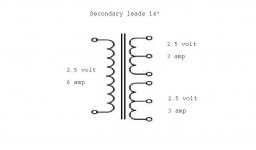
I may have a solution that will fit the amp as it is. If I can find, or have built, an isolation transformer with a single primary capable of 2.5 volts and 6 amps. And two secondaries capable of 2.5 volts at three amps each both with center taps I'd have it made.
Assuming ac heating, if you want to use a single transformer and secondary, get one rated for 2.5 volts at 5-6 amps, and if a centertap is available, use the resistance value of your choice to ground. If a ct is not available, then you are correct that you can use two resistors to make a faux centertap. I think hammond makes a transformer with dual 2.5 volt secondaries, which would allow you to have a single transformer and still have the ability to monitor each tube individually. If you use a single winding, you may find that hum levels can be influenced by which pins you choose to parallel, for example wiring pins 1 to 1 and four to four might show more hum than 1 to four and four to 1, depending on the tubes. ( I found this on a 300B pp amp I built a few years back, wired a switch in so I could reverse the "polarity" of one of the filaments for least hum). The 300b amp gave way to a pp2a3, which I still have and use, it utilizes an individual transformer for each tube, with the centertaps connected to a common cathode resistor.
- Status
- Not open for further replies.
- Home
- Amplifiers
- Tubes / Valves
- PP 2A3 Fixed Bias