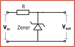
Consider the attached schematic.
I'm of the impression this is a simple and effective way to decrease the supply voltage to one which is within the limits of the op amp. The alternatives would be to regulate the supply or to build a separate one.
This is for small signal only, and maximum output of the op amp is a few volts, loading > 20k impedance.
I would guess this is acceptable, but what is the feeling on this? It's definitely the most efficient solution.
Nearly. You need a resistor/zener arrangement.
Post 1 and 10 here:
http://www.diyaudio.com/forums/power-supplies/259678-will-preamp-supply-work.html
Post 1 and 10 here:
http://www.diyaudio.com/forums/power-supplies/259678-will-preamp-supply-work.html
Nearly. You need a resistor/zener arrangement.
Post 1 and 10 here:
http://www.diyaudio.com/forums/power-supplies/259678-will-preamp-supply-work.html
That's the one plan for a regulated supply, but why won't the above arrangement work?
I see what you want to do but that would not be the way to archeive it. Normally you would want to limit the current through a resistor and then a zener to ground.
There are zener resistor calculators about which would help however a positive (LM317)and negative (LM137) regulators would be a more robust choice.
Cheers
al
There are zener resistor calculators about which would help however a positive (LM317)and negative (LM137) regulators would be a more robust choice.
Cheers
al
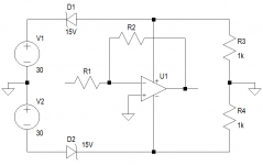
Or, for that matter, why not this?
It will work for sure. The only issue, that this arrangement doesn't make any filtering. All the noise, and supply modulation, -made by the power amplifier- will affect the supply voltage of the preamp.
It can results IM distortion, or even oscillation as well.
Sajti
That's the one plan for a regulated supply, but why won't the above arrangement work?
It would work up to a point. There is no regulation or stability with your arrangement. If the unregulated supply goes up then so to does the opamp supply. It follows the unregulated less approximately the zener voltage. Secondly zeners are 'leaky' devices. If the opamp were a very low current device then then you might find the opamp voltage is much higher than you think.
Easiest solution is to use a 7815 and 7915 with a small 220uF at the output pin and 100nF decoupling cap at input pin. You are good for up to 1amp assuming you don't exceed 35v input.
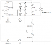
If you still want to use Zeners - a shunt circuit like this will work but only good for about 20mA load. If you need more a shunt transistor circuit needs to be used:
Lots of good stuff here:
http://sound.westhost.com/articles/vi-regulators.html
If you still want to use Zeners - a shunt circuit like this will work but only good for about 20mA load. If you need more a shunt transistor circuit needs to be used:
An externally hosted image should be here but it was not working when we last tested it.
Lots of good stuff here:
http://sound.westhost.com/articles/vi-regulators.html
Last edited:
Thanks. Then for my application, it will work. There's really nothing more to it than it seems. I will just investigate the possibility of oscillations, but I doubt there will an issue.
A regulated supply is overkill, and a zener shunt was my solution, but just chopping off some voltage with a series zener is much easier, and should be fine. The op amp is a quad package and supply current is 7.5mA. PSRR isn't the best, but 100dB is very good.
A regulated supply is overkill, and a zener shunt was my solution, but just chopping off some voltage with a series zener is much easier, and should be fine. The op amp is a quad package and supply current is 7.5mA. PSRR isn't the best, but 100dB is very good.
I prefer to use a resistor/zener shunt operating at a couple milliamps, driving an emitter follower. Less heat than a shunt regulator by itself, which means not having a resistor slowly turning your PCB to carbon over the years. 7815/7915 regulators are nice - until some sort of fault or oscillation in the prototype phase kills every op amp on the board.
until some sort of fault or oscillation in the prototype phase kills every op amp on the board.
I had 4 NE5532's on a board when this happened. Thankfully the chips were fine. 😀
The diodes as in the first schematic work great. The configuration may be contributing to a bit of hum, but I'll diagnose that when I complete my box (this is for my subwoofer build).
Again, thank you all for the input! It's great to learn more, even if it's on a trivial subject like this.
Power supply design isn't trivial. For the sake of a couple of resistors you have compromised the performance of your design many hundredfold.
Using your series zeners, I hope you have not included any supply decoupling of more than perhaps 10 to 47nf in your design across the opamps.
Using your series zeners, I hope you have not included any supply decoupling of more than perhaps 10 to 47nf in your design across the opamps.
Power supply design isn't trivial.
It can be trivial, but it can also get extremely involved.
For the sake of a couple of resistors you have compromised the performance of your design many hundredfold.
Well, potentially not. I agree the zener-shunted regulation would be a better supply. It's just how easy it is to use the series zener, and if it works, then why not? I think it may be contributing to hum, and I'm going to try it out later. Last night I was a bit tired to swap out the power supply.
For a drop from around 20V to 30Vdc to typical opamp supplies of around 15 to 20Vdc, then the R feeding a shunting Zener works very well.
But when the supply voltage is very much higher say 40V to 60Vdc, then I find that the resistor+Zener alone need to be very high power to cover for all the voltage and current variations that can occur.
For very high voltage drops I like to use a series Zener to burn off much of the excess voltage.
Then apply the usual 3pin reg, or R+shunting Zener to feed the variable current demands of the opamps.
I suggested such in a recent Thread and was shouted down, so might be worth doing some experiments before adopting this "way out" solution.
I would NOT use a series Zener to go straight from 30V to 15V straight into the opamp !!! Absolutely not.
Last edited:
That's quite a sound idea. But it all depends on the supply current requirements. The only issues I see with your solution to bleed off a little voltage first is that your power in the first zener is Vz multiplied by the regulator current plus the supply current, which is at least constant, but it is inefficient. Either way, you may as well use another resistor, or just a higher powered one. Another related issue is that if the difference between your series zener voltage and regulated voltage becomes too small, your resistor current will not be able to supply your circuit either. In other words, by doing this, you essentially create supply current ripple which could affect your regulation, so careful design is needed.
The series zener I proposed has the same problems, except that it can (for much more variation) supply the current required.
Either way, I'm going to swap them out for a 7912 and 7812 I have. It's actually a lot easier than using the zener regulator, considering my layout.
The series zener I proposed has the same problems, except that it can (for much more variation) supply the current required.
Either way, I'm going to swap them out for a 7912 and 7812 I have. It's actually a lot easier than using the zener regulator, considering my layout.
You are not making sense.That's quite a sound idea. But it all depends on the supply current requirements. The only issues I see with your solution to bleed off a little voltage first is that your power in the first zener is Vz multiplied by the regulator current plus the supply current, which is at least constant, but it is inefficient. Either way, you may as well use another resistor, or just a higher powered one. Another related issue is that if the difference between your series zener voltage and regulated voltage becomes too small, your resistor current will not be able to supply your circuit either. In other words, by doing this, you essentially create supply current ripple which could affect your regulation, so careful design is needed.
The series zener I proposed has the same problems, except that it can (for much more variation) supply the current required.
Either way, I'm going to swap them out for a 7912 and 7812 I have. It's actually a lot easier than using the zener regulator, considering my layout.
Model some arrangements and see where you have gone wrong with your intuitive estimates.
You are not making sense.
Model some arrangements and see where you have gone wrong with your intuitive estimates.
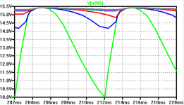
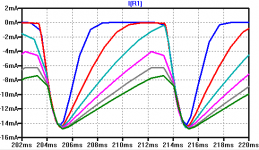
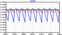
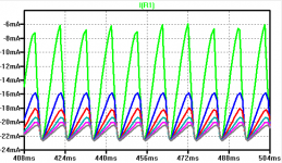
Here are some simulations to show what I mean. Typical power supply for a 60W stereo amplifier, and regulating the main PSU for an op amp circuit, say. Here I used two 15V zeners to exaggerate my results, due mainly to the fact that there is no load on the regulated supply.
Regulated current = 25mA, so the resistor must be 220 ohms.
Attachments
- Status
- Not open for further replies.
- Home
- Amplifiers
- Solid State
- Powering op amps from amplifier PSU