http://www.eserviceinfo.com/downloadsm/33354/QSC_QSC usa370.html
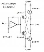
all stages have a gain... (no current stage)
so this can have a brilliant sound 😱 😉
😉
all stages have a gain... (no current stage)
so this can have a brilliant sound 😱
😉Attachments
Thos are not output capacitors, they are the power supply capacitors.
In many of the QSC designs the output/capacitor node is also hooked to the center tap of the power transformer.
In many of the QSC designs the output/capacitor node is also hooked to the center tap of the power transformer.
That is a QSC USA400 PA amp, simple 100w PA amp.
It would make a good sub amp as it is not as refined as
a leach or Self amp. Good for simple first project.
It would make a good sub amp as it is not as refined as
a leach or Self amp. Good for simple first project.
ostripper said:That is a QSC USA400 PA amp, simple 100w PA amp.
It would make a good sub amp as it is not as refined as
a leach or Self amp. Good for simple first project.
The "ripple null pot" is a real giveaway as to it's intended use.
correction
http://www.esafono.it/usa3701.pdf
the original source design have a particular Patent
for output capacitors
See version 3
http://www.esafono.it/usa3701.pdf
the original source design have a particular Patent
for output capacitors
See version 3
Attachments
perfect designs
they have everything .....
-solid rock
- class AB+B topology
-wonderfull sziklai ( output configuration provides also some gain )
-average quality
-extremelly simple to make
-low cost
-soft cliping
-much more effective than class AB +- 15% more
-less heatsink requierd
-with good constuction you may drive extremelly low loads
and from latest expirience they can also drive strange loads without problems but quality remains average at all application
lets face it a simple device may produce all the above but with average quality ....
if i ever meet sziklai i will buy him a case of beers


Attachments
the driver transistors need ~0.7 Volt to start conducting.
But in order to get this, we need ~1 A in the output.
As long as the drivers are not biased
we can not get 1 A in the output.
Result is the circuit will not bias up.
Also the more current in output, the more bias in drivers.
This results in positive feedback and as soon as Vbe of drivers becomes more than like 0.7 Volt
output will be driven into very high current
and output higher and driver higher and output even higher.
Until some transistor(s) will smoke.
We need some other way to make driver bias.
Probably change the idea of this output stage completely.
Maybe you have some other ideas, as well.
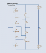
Diamond output stage can also use 4 transistors.
As my attached diagram.
Regards, Lineup
But in order to get this, we need ~1 A in the output.
As long as the drivers are not biased
we can not get 1 A in the output.
Result is the circuit will not bias up.
Also the more current in output, the more bias in drivers.
This results in positive feedback and as soon as Vbe of drivers becomes more than like 0.7 Volt
output will be driven into very high current
and output higher and driver higher and output even higher.
Until some transistor(s) will smoke.
We need some other way to make driver bias.
Probably change the idea of this output stage completely.
Maybe you have some other ideas, as well.
Diamond output stage can also use 4 transistors.
As my attached diagram.
Regards, Lineup
Attachments
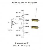
NTC solution
http://www.esafono.it/ntc.pdf
solution is biasing final bases with NTC (glued on dissipator)
that have negative temperature coefficient
so an automatic adjustement of thermal drift 😀
http://www.esafono.it/ntc.pdf
solution is biasing final bases with NTC (glued on dissipator)
that have negative temperature coefficient
so an automatic adjustement of thermal drift 😀
Attachments
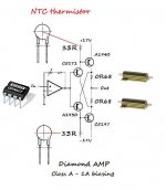
McIntosh does something similar in their late 70s models.
I suggest trying a fixed resistor of 51R with a parallel NTC of 100R.
I suggest trying a fixed resistor of 51R with a parallel NTC of 100R.
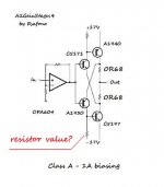
unfortunately it does not matter what type or value you use for those resistors
as i told you, you need 0.7 volt drop from base-emitter of driver transistors
in order to they begin conduct
this requires like 1 A across 0R68 resistors
but how can you get this 1 A, if the drivers do not conduct?
because the drivers will make the 2 output transistors pass current
in short, you should try some other idea, where the drivers can be biased to start conduct current
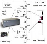
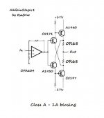
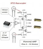
Diamond AMP can exist - THANKS DJK
hello
maybe when power supply start...
biasing start to work
in sincronicity
if you don't like spend money for OPA627
CAN USE TWO OPA604 IN PARALLEL (BIFET)
http://www.esafono.it/diamond amp.jpg
hello
maybe when power supply start...
biasing start to work
in sincronicity
if you don't like spend money for OPA627
CAN USE TWO OPA604 IN PARALLEL (BIFET)
http://www.esafono.it/diamond amp.jpg
Attachments
It is going to need some more parts to make it work.
I would suggest reading the TubeCad thread on the Moskido.
I would suggest reading the TubeCad thread on the Moskido.
- Status
- Not open for further replies.
- Home
- Amplifiers
- Solid State
- Powered OPA amplifier