It is very likely that it is a passive line level crossover. No active devices required. The 9v is passed through or not used at all.
It is very likely that it is a passive line level crossover. No active devices required. The 9v is passed through or not used at all.
Or it's some sort of shut of mechanism in case the crossover gets removed???
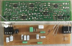
Kind of a dead-man switch. And what IS that little round black thing? Looks like a mini bridge rectifier, but obviously wrong number of pins.
I tried it today with a 20v linear transformer, but the music still sounded distorted. Maybe a ground problem?What power supply did you use? Some are designed for a constant load and cannot handle audio amplifiers. As there was at least some sound coming through when you tested the amplifiers, the amplifiers might still to be OK.
I would try to use a different power supply, preferably a linear one (transformer, bridge rectifier, electrolytic capacitors), as these always work with audio amplifiers.
Interesting idea. I'll try it out tomorrow and see if it works without the 9vThat's interesting. I don't see any active devices on the crossover board, and the schematic as well (thought it is cut off on the left).
I also can't quite tell what that little black thing is. Is it a buzzer? A thermal cut off of some sort?
It seems like it gets +- 9 V but it doesn't do anything with it. This could be due to the same connectors/amp being used with a variety of crossovers, or the crossover started as fully active, then was altered.
I downloaded the supposed "service manual" from Elektrotanya, chock full of setup adjustments, screen pictures, patterns https://elektrotanya.com/cgi-bin/do...3&file=bang_olufsen_beovision_avant_32dvd.pdf ... but NO schematics ... WTF?
And every two pages they mention "board replacement" or "chassis replacement" ... WTF????
And every two pages they mention "board replacement" or "chassis replacement" ... WTF????
Morten: Before you burn anything out, why don't you look at the traces, see if those pins go anywhere?
It's an active crossover as there are heaps of 4558 op amps. You get a better idea when you see both sides of the board together so you can see where the film caps on one side line up in the circuit. The round black thingy sits above C1 on the other side and the exposed leads you see are above the C1 designation. So it must be a capacitor or super capacitor.
Attachments
Last edited:
I suggest you rewire your speakers with passive cross-overs.
Amazon.com: uxcell 2 Pcs 130W 2-Way Speaker System Audio Crossover Filters Frequency Distributor: Gateway
Amazon.com: uxcell 2 Pcs 130W 2-Way Speaker System Audio Crossover Filters Frequency Distributor: Gateway
I got them powered on today, but the extra cables and power supply that it requires is just not worth it. I’ll just make a new pair of passive crossovers to use with the speakers. It was a fun experience to try and make it work, so the time was not wasted. Thanks for the help guys!
- Status
- Not open for further replies.
- Home
- Loudspeakers
- Multi-Way
- Powered Crossover?