It will likely only stress the driver circuit more.
Without better support for the board, these amps break the output transistors off where the transistors meet the board.
Without better support for the board, these amps break the output transistors off where the transistors meet the board.
Are there muting transistors in this amp ?
Wondering since when I power off the amp I get a thump thri the test speaker ..
Or anyone know what might cause this ?
Wondering since when I power off the amp I get a thump thri the test speaker ..
Or anyone know what might cause this ?
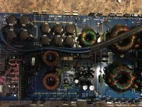
Anyone know where the weak points are in this amp? I re flowed the solder on the driver board ,rectifiers, inductors, ..
The problem I'm having is if I tap the circuit board lightly the sound will cut out and if I tap it again the audio will come back.
I can't seem to find what's causing this ..
The problem I'm having is if I tap the circuit board lightly the sound will cut out and if I tap it again the audio will come back.
I can't seem to find what's causing this ..
Powerbass ASA1500.1D
...so what about amplifier of this design in nature that has 12 to 16 fets installed?
...or what about replacing the full TO-92 package driverboard with the TO-220(isolated) package driverboard and install the 4 fets, would that be more of an upgrade than a modification?
...so Mr Babin, youre saying if the 4 fets is added to the existing line-up it will have a likely higher probabilty of failure?It will likely only stress the driver circuit more.
Without better support for the board, these amps break the output transistors off where the transistors meet the board.
...so what about amplifier of this design in nature that has 12 to 16 fets installed?
...or what about replacing the full TO-92 package driverboard with the TO-220(isolated) package driverboard and install the 4 fets, would that be more of an upgrade than a modification?
If you have any other questions on this, have the moderator move your question to a new thread. Include a link to this thread.
The driver boards have a much higher rate of failure driving 10 FET. Driving 12 would be worse.
I've found the board with the larger transistors worse. It appears that the larger transistors are slower and cause their own problems. The two transistors that replaced Q124 and Q125 still overheat on the TO-220 board.
10 years ago, soundstream used the TO-92 driver board with outboard drivers and it worked perfectly. I guess the extra $0.30 worth of parts upset the bean counters.
Again, have this moved if you have any more questions.
- Status
- Not open for further replies.
- Home
- General Interest
- Car Audio
- Powerbass ASA 1500.1D