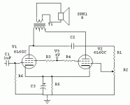
I was thinking about how to make a poweramp without using a tube phase splitter. I already made a good performing solid-state one. Then I thought of something else. Why not throw away the entire phase splitter. The drawing I made says it all. It's probably not new, but why haven't I encountered it yet in some cheap tube stuff? Maybe I'm overlooking some reason why it can't work.
I see that it probably won't be high quality as the distortion of the first tube is amplified by the second and the phase shift to the second tube won't be exactly 180°
Anyway I'll try it if I find some spare time.
I see that it probably won't be high quality as the distortion of the first tube is amplified by the second and the phase shift to the second tube won't be exactly 180°
Anyway I'll try it if I find some spare time.
Attachments
i know nothing about this kind of thing but I don't see a negative voltage port on there anywere. where's the current going to flow?
I know nothing about amplifiers. Just my naive observation.
I know nothing about amplifiers. Just my naive observation.
Minimalist power amp...
Hi Svokke
Interesting ideia...the distortion perfomance wouldn't be great...the damping factor will be near 0...it need a pre amp with high voltage output swing...but it will work.
Cheers
Hi Svokke
Interesting ideia...the distortion perfomance wouldn't be great...the damping factor will be near 0...it need a pre amp with high voltage output swing...but it will work.
Cheers
I think you can make it even simplier:
Remove C2, R1 and C3.
R5 can be changed to a constant current source.
Do this and you have what´s called a selfsplit power amp.
Remove C2, R1 and C3.
R5 can be changed to a constant current source.
Do this and you have what´s called a selfsplit power amp.
I've done that before in a guitar amp, but someone told me it is limited to class A amps. I don't see why it should be limited to class A amps though.I think you can make it even simplier:
Remove C2, R1 and C3.
R5 can be changed to a constant current source.
Do this and you have what´s called a selfsplit power amp.
I also think that the gain from my topology is larger, as the cathode resistor can be bypassed by C3.
I also think that the gain from my topology is larger, as the cathode resistor can be bypassed by C3.
Yes..the gain from your topology is larger and the output impedance will be lower...
it's been done before (no phase splitter)
these could be of help -
http://www.triodeel.com/compact.html

http://www.diyparadise.com/simpleel84.html
these could be of help -
http://www.triodeel.com/compact.html

http://www.diyparadise.com/simpleel84.html
An externally hosted image should be here but it was not working when we last tested it.
arnold,
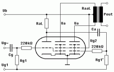
That topology accomplishes the phase split differently... here is a map of a single tube designed to do what svokke is illustrating (uses a unity gain triode section instead of an external pot to invert phase)... the tube is the Lorenz ECLL800 -- a single tube good for an 8 W PP tube amp.
dave
That topology accomplishes the phase split differently... here is a map of a single tube designed to do what svokke is illustrating (uses a unity gain triode section instead of an external pot to invert phase)... the tube is the Lorenz ECLL800 -- a single tube good for an 8 W PP tube amp.
dave
Attachments
hi dave, thank you for another bit of education. now i know that amps without a phase splitter still differs in topology. 🙂 so much to learn, indeed.
cheers!
cheers!
planet10 said:instead of an external pot to invert phase
I should add that the pot doesn't invert the phase, it just allows you to adjust the inverted output of the 1st EL84 to give appropriate grid drive to the 2nd one.
dave
- Status
- Not open for further replies.
- Home
- Amplifiers
- Tubes / Valves
- poweramp topology

